Filter hacking for 2395 ISS TV

S-Band DVB-S from the International Space Station
radiogareth
Posts: 1407
Joined: Wed Jan 06, 2016 9:46 am

Filter hacking for 2395 ISS TV

Post by radiogareth » Fri Oct 31, 2025 4:28 pm

Having been sparked into action as a result of Phil and Jens CAT25#2 talk, I raided my 'possibly useful ' filter pile and spent some time trying to tweak them for a useful passband centred on 2395MHz. Neither were suitable as-removed from service, but after a while spent screwdriver tweaking I have ended up with this passband.
-33dB at 2390, 7dB insertion loss (two filters in series) -14dB at 2400.
A G4DDK preamp should overcome the loss and the low side cut-off might just shut out the 5G.
Thoughts welcome....
No I have not found the screws to move the unwanted peaks elsewhere, but other than resonance and coupling (hidden behind 60+ torx screws) they have all had a good old tweak to see if I could....
All done with Satsagen :-)
Gareth
2395_notch_dual.jpg
2395_notch_dual.jpg (128.49 KiB) Viewed 421 times

g4hiz
Posts: 115
Joined: Thu Oct 18, 2018 6:40 am

Re: Filter hacking for 2395 ISS TV

Post by g4hiz » Sun Nov 02, 2025 9:04 am

Gareth,

Don't forget the other main objective here and that is to get the required passband at 2395MHz and this is where a close-in plot covering say 50MHz would be useful. The signal bandwidth is about 2.7MHz, but if you have a filter that narrow then phase distortion at the filter edges will most likely introduce symbol errors. In practice, I found that a 10MHz bandwidth filter worked well.

It would be useful if you are able to show a photo of the filter that you have tried re-tuning. The one that I used for my system had 5 poles and I didn't adjust anything other than the pole tuning and it gave good results. If there are lots of poles things become more difficult quickly and with two filters in series, very tricky, especially if not using a VNA of some sort. It would be also useful to see a sketch of the test set-up.

The filter terminations are important for a couple of reasons. If you tune-up in a 50 Ohm system then add some random RF component at either end then the passband will be affected, with passband ripple and slope being common. Adding a circulator at each end would give the best results, but probably not available in the spares box. The next best thing is to add an attenuator at each end as this improves the match. Now the second reason for matching, if you hang a high gain RF amp on the output of the filter, then you can bet that a some frequency, the amp will most likely oscillate due to having just enough gain and mismatch at that frequency. My own system initially oscillated at 3.7GHz and this was cured by adding a 3dB attenuator after the filter.

73
Jen
Last edited by g4hiz on Mon Nov 03, 2025 7:31 am, edited 1 time in total.

g0mjw
Posts: 2670
Joined: Sat Sep 20, 2014 9:15 am

Re: Filter hacking for 2395 ISS TV

Post by g0mjw » Sun Nov 02, 2025 9:40 am

A agree with Jen,

That response does not look good. It looks like some more or less random tweaking rather than a systematic tune up. Satsagen is good but it is not giving you the phase information. The way I do it is to use a VNA and look at the Smith chart for alternating 180 degree phase shifts at the design frequency. That's by far the easiest way to do this.

However you don't have a VNA so the Dishal method is probably the best way. That involves detuning all the other resonators except the one you are trying to tune and then peaking that one. You can detune them by shorting them out, but in your typical tuning screw filter that's not easy, so once you have tuned it, simply de-tune it by a known amount, e.g. 1 turn clockwise, or more turns if needed and remember where it should be using pen and paper to take notes. Repeat for all the other resonators.

Once you have found the resonance of all the filters, then you can set them all back to where they ought to be. At that point, it will be close to on frequency.

You can't adjust the coupling in this way, best not touch the coupling screws if there are any. You are not moving it very far, so they should be OK already. Too late now I expect. If you have moved them, put them back using the high resolution photo you took before starting, or using other clues like evidence of exposure to air etc.


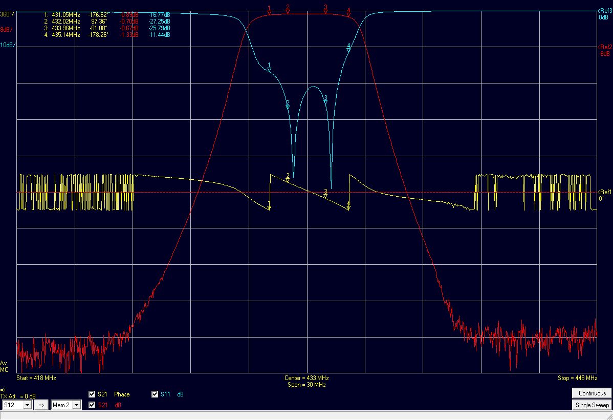
Edit - here is one I did earlier, it was originally somewhat below 70cm with I thing 6 resonators (might be 8, cant remember) that each consisted of a cavity with a disc on the end of a post tuned against the far end of the cavity (i.e. like a disc capacitor). I had to turn down the discs a bit to move it up in frequency. I then retuned it using alternating 180 degree phases in S21 (or S11 if you don't have S21). This was the result:
filter_tuning_26463138126_o.jpg
filter_tuning_26463138126_o.jpg (103.05 KiB) Viewed 294 times
Not perfect, but good enough.

Mike

radiogareth
Posts: 1407
Joined: Wed Jan 06, 2016 9:46 am

Re: Filter hacking for 2395 ISS TV

Post by radiogareth » Sun Nov 02, 2025 11:29 am

Thanks both for the input and yet more learning/reminding about what matters.
Both filters can be returned to stock and I'll have another go at it. Busy elsewhere all this coming week so won't get to play radio and will then perhaps gravitate to using the NanoVNA-V2 that I have but don't fully understand its deeper operation.
Pictures of the two filters I have attached.
Speaking to John G8MNY who mentioned using a circulator with a ?tunable tap on one of the ports as an effective method. Found this article about the method but I need to read it several times to try and understand whats going on. https://par.nsf.gov/servlets/purl/10309515 That and 1/4 wave stubs maybe, but perhaps not narrow enough.
Still, its fun to experiment....
Gareth
IMG_20251102_112656427_HDR.jpg
IMG_20251102_112656427_HDR.jpg (109.51 KiB) Viewed 278 times
Smaller filter.jpg
Smaller filter.jpg (244.83 KiB) Viewed 276 times

Basil
Posts: 411
Joined: Tue Sep 10, 2013 7:28 pm

Re: Filter hacking for 2395 ISS TV

Post by Basil » Sun Nov 02, 2025 11:36 am

There are a lot of interactive things to twiddle there.... Looks daunting!
Best regards,

Chris, 2E0ILY in rural Shropshire.

radiogareth
Posts: 1407
Joined: Wed Jan 06, 2016 9:46 am

Re: Filter hacking for 2395 ISS TV

Post by radiogareth » Sun Nov 02, 2025 12:46 pm

Yes, AFAIK the screws that are between the pillars are coupling and the ones inside resonate each column. But what are the little link-straps pieces doing....linking some of the energy down to the bottom pair......it came out of a UMTS 2.1-2.2GHz big pa (4 devices) then into a circulator then output N-type. If only I had the user manual ;-)
Gareth

radiogareth
Posts: 1407
Joined: Wed Jan 06, 2016 9:46 am

Re: Filter hacking for 2395 ISS TV

Post by radiogareth » Sun Nov 02, 2025 4:02 pm

This is a re-tuning article about the larger filter I have. If it could be tuned up narrower rather than just moved it would be wonderful.
"Work in progress"....
https://www.dd1us.de/Downloads/Retuning ... 20rev1.pdf
Gareth

g0mjw
Posts: 2670
Joined: Sat Sep 20, 2014 9:15 am

Re: Filter hacking for 2395 ISS TV

Post by g0mjw » Sun Nov 02, 2025 6:03 pm

I looked in my box of filters and came across this old UHFComs design, it has only three tuneable elements and was on 2320 MHz. A very quick re-tune with a VNA gave the results shown. A filter like this is easy to make. It it basically aluminium channel with some post resonators and tuning caps that wind in and out.
2395MHz filter.jpg
2395MHz filter.jpg (1.09 MiB) Viewed 229 times
Here is a narrow response.
Filter_1.jpg
Filter_1.jpg (80.34 KiB) Viewed 229 times
And a wider one
Filter_2.jpg
Filter_2.jpg (82.28 KiB) Viewed 229 times
and the phase - note the sudden flips are simply going through 360 degrees. What you want to see is smooth variation.
Filter-4.jpg
Filter-4.jpg (219.54 KiB) Viewed 228 times
and I suppose a smith chart is always nice to see
Filter-5.jpg
Filter-5.jpg (238.09 KiB) Viewed 226 times
So not too bad, probably not sharp enough but it would help. The loss is 0.7 dB. The -20 dB bandwidth is 60 MHz and the passband around 20 MHz.

Tuning a filter narrower means changing the coupling and ideally a re-design. If you can, reduce the coupling to narrow it. For a post filter like the one above, that generally means moving the posts further apart. With filters like you have with adjustable coupling, it probably means adjusting the coupling screws out a bit.

Mike

g4eml
Posts: 772
Joined: Thu Apr 26, 2018 9:36 am

Re: Filter hacking for 2395 ISS TV

Post by g4eml » Sun Nov 02, 2025 9:29 pm

I am planning to make a couple of similar filters from the designs by S53MV

http://s53mv.s5tech.net/cavity/cavity.html

I have previously made some of the 23cm versions and they tuned up and behaved very well.

Colin G4EML

radiogareth
Posts: 1407
Joined: Wed Jan 06, 2016 9:46 am

Re: Filter hacking for 2395 ISS TV

Post by radiogareth » Mon Nov 03, 2025 7:06 am

All good stuff, just need to find some alloy tubing of the required size.
Gareth

Post Reply

Return to “ARISS HamTV”