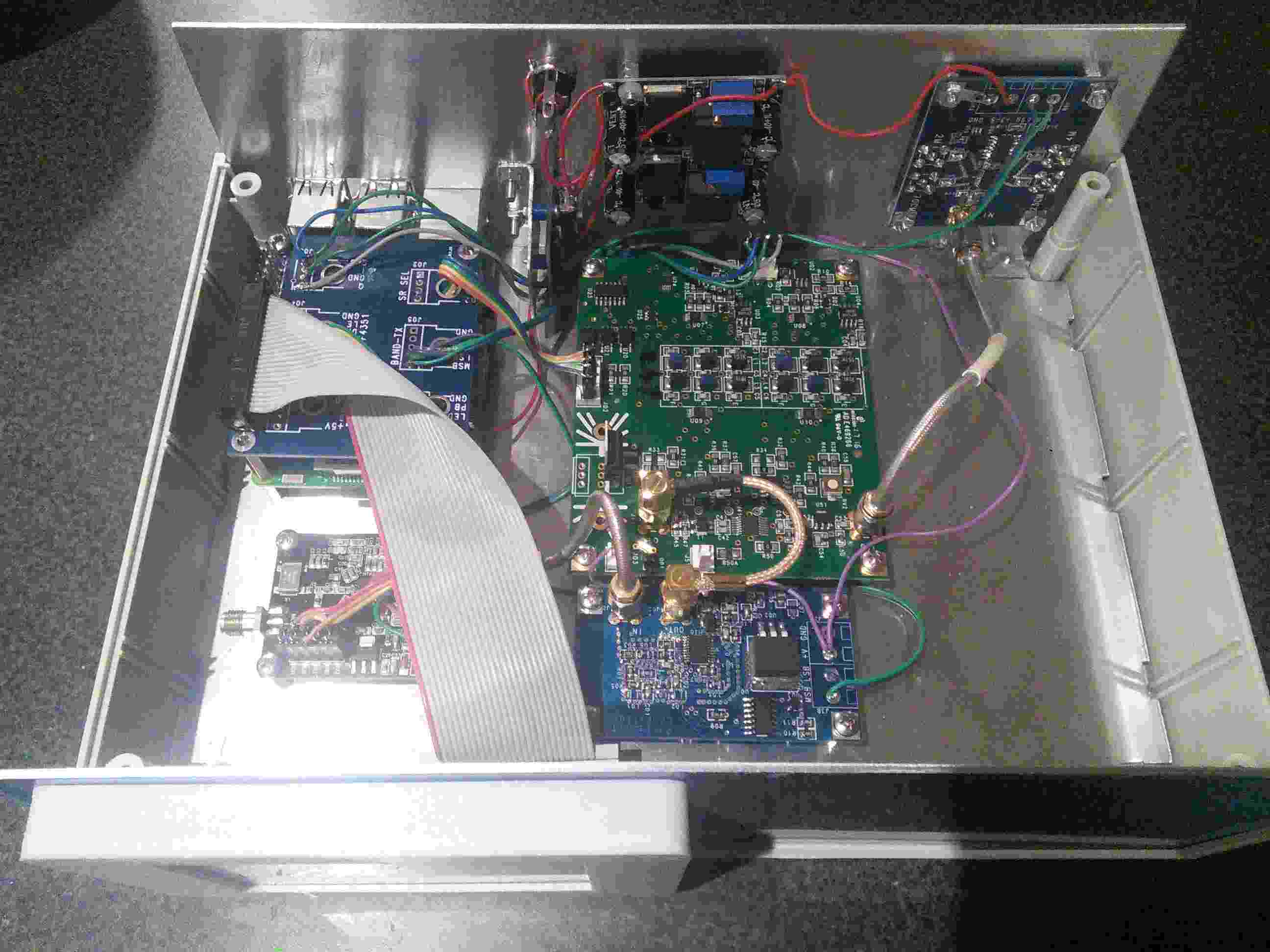
A picture of the G4FRE build.
I wanted some screening, hence the metal chassis and panels in the plastic box.
I used two smps power units; one set to 5,2V for the RPI and output rf switch and one set to 8V for the DDS, Lo filter and FM. I have left space for more modules e.g. the programmable attenuator and a custom amplifier switch/controller
After having issues with supplying power to the RPI through the microusb connector I soldered power leads directly to the board. This fixed the issue

- g4fre_build.jpg (148.91 KiB) Viewed 5516 times