I am trying to drive an RA18H1213G brick amp from my digilite board. In FM service this amp runs sweetly at well over 20W out all day without getting too hot. Due to the low level output of the DigiLite some extra gain is required to drive the brick amp. I have tried a number of driver amps with the DigiLite including a VNA25 , SPF5043Z, and an ATF50189 (the MiniKits 1W amp) in various combinations. The VNA25 or SP5043Z both work well as a first stage but not enough drive for the brick amp. Adding the ATF50189 I get plenty of output and good linearity at 50mW or more. I have a switched attenuator in line to adjust drive. The problem is that when when I add the brick amp it all goes pear shaped. Spectral regrowth above about 2W out with visible signs of peak compression. In CQ-TV 235 a table shows optimum linear mode bias for this brick to be 4V with 0.9A quiescent current so I tried to stick to these settings. I have read here of others getting 10W out so what are they doing differently? Are they running a different bias? If so what level of quiescent current are others using on their RA18H1213G?
Any comment?
Dick G4BBH
Digilite and the RA18H1213G
Re: Digilite and the RA18H1213G
Not sure if this helps exactly but the unit i built which is out on loan uses the RA18H1213 module and will produce 10W or more before regrowth becomes a problem. The bias setting i used is the nominal value specified for the device (sorry can't remember the value)
The single buffer amp i use between the digilite and PA brick is capable of nearly 100mW which is more than enough to drive the brick to 10W.. it is the SBA-5086Z but the others you have tried will do similar P1dB power and gain so should be ok.
It's possible the whole setup is becoming unstable and you are possibly getting feedback to the input due to having the high gain through the amplifiers. which will be around 50 to 60dB in total!
One thing to note is that the digilite is more linear (and has higher output) with the drain inductor(and cap) fitted directly at the MAR-6 rather than up the track.
This may enable you to use just one amplifier instead of two.
Hope that is useful...!
Rob
M0DTS
Re: Digilite and the RA18H1213G
Hi
Like Rob , I ignored the optimum bias point and use a 5v regulator to supply the bias, I run it at maximum bias at 5v,(maybe 4.95v) , and adjust only the rf drive to the RA18H1213G block, I get 9watts before onset of serious regrowth, 11watts with bad regrowth. My rf drive is low 10mW ish coming from the digilite even with its mmic output stage , and I then use a 3db attenuator to reduce drive further. If I over drive (>25mw) I get 20Watts, but terrible regrowth. So Less is good in this situation and ignore the optimum bias.
Rob is right about possible feed back too, decouple and screen the block well, and don't drive it too hard.
hope this helps too.
Richard g8byi
Re: Digilite and the RA18H1213G
Another thing to note is that if the output match from the module (coax to the socket) is poor then this can cause the non linearity you are seeing too.
One test for this will be to drive the brick to saturation, if you can acheive ~30w then the output connection can be assumed to be working correctly, otherwise saturation point will probably be significantly lower and you might only get 20W or less but i think you have done 20W plus already.
A check of current comsumption will be useful here too.
Thought it may be useful info..hi
Rob
Re: Digilite and the RA18H1213G
Rob
It looks as if I might have a problem with my brick amp. I get about 22W out with 18dBm drive and 13.5V supply and this seems to be saturated. Was never a problem when driven by the FM TX. This amp is built using the Mini-Kits PCB. The ouput feeds via about 1" semi flexible hardline to an N-type connector on the side of the diecast box. Should be no losses there but there may be losses at the output lead of the module to PCB. As the PCB is mounted flush to the heatsink adjacent to the Mitsubishi module the output lead from the module is over 1mm above the board and had to be bent down to the output track on the board. This leaves around 1.5mm of lead between the module and track. Could this cause such losses? If so will have to put an aluminium shim between the board and heatsink to raise it to the same level as the module connections. That will mean I will have a problem fitting the ferrite beads that Mini-Kits specify on the power connections.
Sorry, have not sussed out how to add an image of this.
Dick G4BBH
Re: Digilite and the RA18H1213G
I built mine teh same way onto a heatsink, bending the RF connections down does not appear to cause much of a problem.
Also be careful of the DC power cable you use, they could be dropping a lot of voltage if very low current rating and cusing the power to be lower.
I can't gaurantee you will get ~30W out of the module, i've never tried it myself! but I'm just going by the datasheet an what others have said.
When you drive the amp with the FM tx what power do you get and is that a different frequency to where you are using the digital?
Rob
Uploading attachments is quite easy, below the message entry box there are two tabs - Options and Upload attachment
Re: Digilite and the RA18H1213G
OK Rob. Running all tests at 1280MHz as above that the gain will drop although a sweep shows still useful at over 1300MHz. For FM I am checking using a modified Comtech TX as I have a controller to set any frequency as does the BYI board on my DigiLite. With 18 dBm of FM drive I am getting just about 21W out, a gain of about 25 dB. I could drive it a little harder on FM but never bothered as the official rating is 18W.
I did find the supply fuse I fitted to the PA dropped too much voltage and had to replace the fuse holder with a better design but is still around 180mV at full power. The PA is in a diecast box and DC input is via a high current feedthrough capacitor so little RF leakage. I have tried playing with bias to the module and I am getting best linear power out when using 4.2V bias. I think I will just run at the best linear power I can and leave it at that for now. I can probably get away with a little non-linearity. RX quality on the receiver sticks between 88 and 90 until the spectrum analyser starts to show significant high order products (7th and above) .
It was much easier to get linearity and power with valves but gave that up after several failed attempts at self electrocution ( the XYL says I never get anything right).
Dick G4BBH
Re: Digilite and the RA18H1213G
OK.. yes best stick with what you have for now, would be interesting for you to compare results if anyone else locally to you builds the same setup.
I have run out of ideas, maybe there is a lot of variation of max power output with the modules that we are not aware of...
I notice i can go to a high level of spectral regrowth before the receiving station sees a problem, very often more power helps even if poor linearity!
I've tested this into GB3KM on occasions where i'm running at nearly full output of my amplifier (IMD3 only -20dBc!) on digital and just getting a stable signal into the repeater, if i drop power even by a small amount i cannot access even though the IMD3 improves by over 10dB! quite amazing really!
Rob
Re: Digilite and the RA18H1213G
I made a buffer from 0dBm to about 24dBm. All parts are currently in production. I created a small PCB for it, which you can place in a 37x37mm tin can. It works perfectly with my Philips DVB-S modulator. Spectrum is clean.
I have a few PCB's available, these are professional PCB's with silkscreen.
Schematic:
http://www.zendamateur.com/download/file.php?id=6911
I have a few PCB's available, these are professional PCB's with silkscreen.
Schematic:
http://www.zendamateur.com/download/file.php?id=6911
- Attachments
-
- ampje.jpg (177.79 KiB) Viewed 15337 times
Re: Digilite and the RA18H1213G
Here is another inexpensive board for building an amp to boost the signal from the DigiLite to the RA18H1212G. It's easily snapped apart into four 1" x 1" boards.
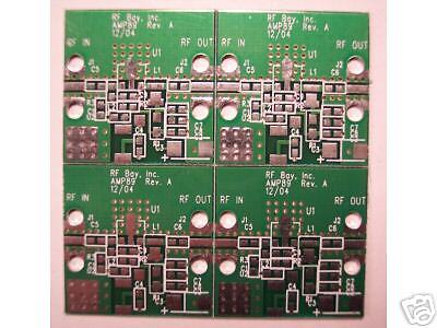
http://www.ebay.com/itm/Develop-PCB-RF- ... 500wt_1156
Here are suggested values and component sizes and DigiKey part numbers too.
C02, C07 -- 1000 pF -- 603 -- 587-1069-1-ND
C03 -- 10uF -- 1206 -- 311-1465-1-ND
C04 -- 0.1uF -- 805 -- 399-1170-1-ND
C05, C06 -- 82 pF -- 603 -- 712-1367-1-ND
C08 -- 47 pF -- 603 -- 712-1354-1-ND
L01 -- 30nH -- 603 -- A103733CT-ND
R01 -- 68 -- 1206 -- P68.0FCT-ND
U01 -- SGA-5589 -- SOT-89 -- 599-1045-1-ND
U02 -- LM78M08 -- DPAK -- MC78M08CDTRKGOSCT-ND
Also I replaced the mmic on the DigiLite with a SGA-5589. R26 and R41 were replaced with a single 68 ohm size 1206 resistor. With this combination the output of the RA18H1212G is about 16 watts.