I'm working on a digital Nyquist filter for DigiLite at the moment. Each of the two I/Q channels has a dsPIC, a DAC and an opamp.
I've only built one channel so far, so I've only seen the analyser output at baseband. All other things being equal, it looks like the transmitted width at SR4000 should be about 6MHz where it hits the deck.
Brian
TX Noise
-
F1CJN_alain
- Posts: 90
- Joined: Thu Jul 21, 2011 9:50 am
Re: TX Noise
This is my output spectrum with the decoupling caps on the regulators and video, plus the 68pF capacitor on the V+ supply of the O/P voltage stage of the Ultram VCO.
Alain
F1CJN
Alain
F1CJN
- Attachments
-
- Digilite Spectrum
- Digilite_spectrum.JPG (89.19 KiB) Viewed 6331 times
Re: TX Noise
Hi Alain,
It looks very similar to mine just you have better dynamic range to see the noise!
is that with Carrier only or running with Data?
Rob
It looks very similar to mine just you have better dynamic range to see the noise!
is that with Carrier only or running with Data?
Rob
Re: TX Noise
Some more pictures. Thanks to G3UVR for the analyser.
I've made all the decoupling mods suggested above and elsewhere, plus 100nF across the opamp supply pins 4 and 8, plus 100nF across C33. I also put a via in at the earthy end of C25. I'm using an MSA-0886 instead of a MAR-6 and an external BGA6589 stage giving 10mW PEP output (single carrier).
Below is the LSB test. LO/USB 39dB/38dB down on PEP.
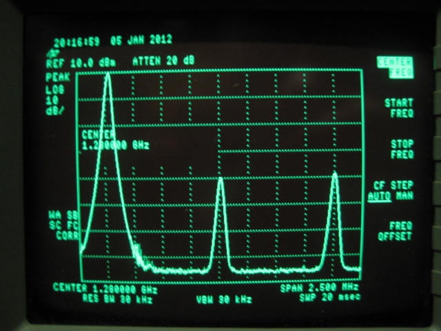
Below is the USB test. LO/LSB 39dB/38dB down on PEP.
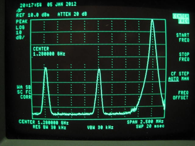
Below is the In Phase test. LO 44dB down on PEP. Each sideband is 3dB down, as the power is split between them.
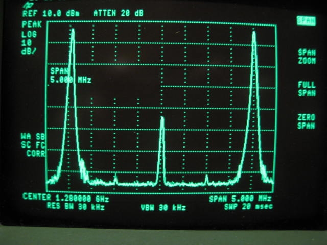
Below is normal modulation.
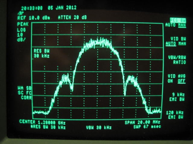
Below is normal modulation over +/- 100MHz.
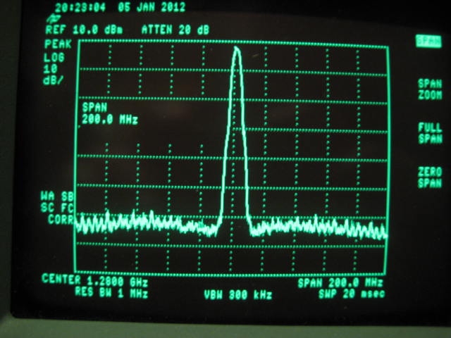
Not being used to an analyser, I was puzzled as to why the noise increased on the wide plot. If I understand it correctly, you can't specify the level of the noise unless you specify the bandwidth you're measuring it in. The RBW (resolution bandwidth) bottom left is presumably the width of the analyser receive filter as it scans. The RBW for the wide plot is 1MHz and 30kHz for the others, a factor of 30 or 15dB, which is the about the difference in noise between the plots.
Brian
I've made all the decoupling mods suggested above and elsewhere, plus 100nF across the opamp supply pins 4 and 8, plus 100nF across C33. I also put a via in at the earthy end of C25. I'm using an MSA-0886 instead of a MAR-6 and an external BGA6589 stage giving 10mW PEP output (single carrier).
Below is the LSB test. LO/USB 39dB/38dB down on PEP.
Below is the USB test. LO/LSB 39dB/38dB down on PEP.
Below is the In Phase test. LO 44dB down on PEP. Each sideband is 3dB down, as the power is split between them.
Below is normal modulation.
Below is normal modulation over +/- 100MHz.
Not being used to an analyser, I was puzzled as to why the noise increased on the wide plot. If I understand it correctly, you can't specify the level of the noise unless you specify the bandwidth you're measuring it in. The RBW (resolution bandwidth) bottom left is presumably the width of the analyser receive filter as it scans. The RBW for the wide plot is 1MHz and 30kHz for the others, a factor of 30 or 15dB, which is the about the difference in noise between the plots.
Brian
Re: TX Noise
Hi Brian,
Yes it looks like your plots match up with mine regarding the noise at around -55dBc.
I did not know much about RBW before i played with digital stuff either but that is true RBW is the bandwidth of the spec-an receiver, A power meter on the other hand is very wide band and will measure everything including harmonics etc so sometimes makes readings a little optimistic!
When trying to measure rough power on an analyser with a digital signal it is not quite possible at 4Ms as most analysers only go to 3MHz RBW but fine at 2Ms and below.
Rob