Page 4 of 5
Re: ULTRAM VCO
Posted: Tue Apr 24, 2012 8:29 pm
by G0MXW
Guy, my fault....got byte order mixed up.
Also you only need to toggle the LE after 3bytes of data sent. Amended code snippet below:-
Code: Select all
  digitalWrite(slaveSelectPin,LOW);
  WriteADF(0x30,0x01,0x91);    //R
  delayMicroseconds(2500);
  WriteADF(0x8F,0xE9,0x24);    //Func
  delayMicroseconds(2500);
  WriteADF(0x01,0x8E,0x3A);    //N
  SPI.end();
}

int WriteADF(byte a1, byte a2, byte a3) {
  SPI.transfer(a1);
  SPI.transfer(a2);
  SPI.transfer(a3);
  Toggle();
}
Dave
G0MXW
Edited: to fix code tags on 2012-04-25 by gm1mfn.
Re: ULTRAM VCO
Posted: Tue Apr 24, 2012 9:29 pm
by on4bhm
thanks, it works now !!!
now i can start converting the c# code to arduino code
and after that make the user interface with display and buttons to change the freq.
thanks
Re: ULTRAM VCO
Posted: Mon Apr 30, 2012 12:45 pm
by on4bhm
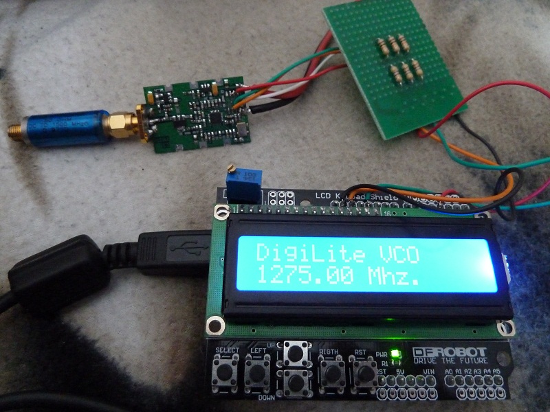
- P1000606.jpg (187.21 KiB) Viewed 27186 times
I have some sample code ready for the arduino.
With the up and down button you can change the freq in steps of 500 khz.
There are no boundaries for the freq at the moment.
start freq is 1250Mhz
Source is free to use and to adapt.
Menu has to be implemented...
Source code listing here:
Code: Select all
// inslude the SPI library:
#include <LiquidCrystal.h>
#include <SPI.h>
#include <PString.h>

// set pin 10 as the slave select for the digital pot:
const int slaveSelectPin = 3;
// select the pins used on the LCD panel
LiquidCrystal lcd(8, 9, 4, 5, 6, 7);
// define some values used by the panel and buttons
int lcd_key     = 0;
int adc_key_in  = 0;
#define btnRIGHT  0
#define btnUP     1
#define btnDOWN   2
#define btnLEFT   3
#define btnSELECT 4
#define btnNONE   5
unsigned long Reg[3];
float Freq;
float Step;

void setup() {
  lcd.begin(16, 2);              // start the library
  lcd.setCursor(0,0);
  // set the slaveSelectPin as an output:
  pinMode (slaveSelectPin, OUTPUT);
  digitalWrite(slaveSelectPin,LOW);
  // initialize SPI:
  SPI.setDataMode(SPI_MODE0);
  SPI.setBitOrder(MSBFIRST);
  SPI.setClockDivider(SPI_CLOCK_DIV128);
  SPI.begin();
  lcd.print("DigiLite VCO");
//  SPI.end();
  Freq = 1250;
  Step = 0.5;
  SetFreq(Freq);
}

void loop() {
  //lcd.setCursor(9,1);            // move cursor to second line "1" and 9 spaces over
  //lcd.print(millis()/1000);      // display seconds elapsed since power-up


  lcd_key = read_LCD_buttons();  // read the buttons

  switch (lcd_key)               // depending on which button was pushed, we perform an action
  {
    case btnRIGHT:
      {
       break;
      }
    case btnLEFT:
      {
       break;
      }
    case btnUP:
      {
       Freq = Freq + Step;
       SetFreq(Freq);
       break;
      }
    case btnDOWN:
      {
       Freq = Freq - Step;
       SetFreq(Freq);
       break;
      }
    case btnSELECT:
      {
      //lcd.print("SELECT");
      break;
      }
      case btnNONE:
      {
      //lcd.print("NONE  ");
      break;
      }
  }
}
void SetFreq(float Freq)
{
       delay(100);
       char buffer[15];
       PString mystring(buffer, sizeof(buffer));
       mystring.print(Freq);
       mystring.print(" Mhz.");
       lcd.setCursor(0,1);            // move to the begining of the second line
       lcd.print(mystring);
       delay(100);
       ConvertFreq(Freq,Reg);
       WriteADF2(1);
       delayMicroseconds(2500);
       WriteADF2(0);
       delayMicroseconds(2500);
       WriteADF2(2);
       delayMicroseconds(2500);
}
void WriteADF2(int idx)
{
   byte buf[5];
   for (int i = 0; i < 4; i++)                         // "i < [Bits per register / 8]"
     buf[i] = (byte)(Reg[idx] >> (i * 8));
   WriteADF(buf[2],buf[1],buf[0]);
}
int WriteADF(byte a1, byte a2, byte a3) {
  // take the SS pin low to select the chip:
  digitalWrite(slaveSelectPin,LOW);
  delayMicroseconds(10);
  SPI.transfer(a1);
  SPI.transfer(a2);
  SPI.transfer(a3);
  Toggle();
}

int Toggle() {
  digitalWrite(slaveSelectPin,HIGH);
  delayMicroseconds(1);
  digitalWrite(slaveSelectPin,LOW);
}

// read the buttons
int read_LCD_buttons()
{
  adc_key_in = analogRead(0);      // read the value from the sensor
 // my buttons when read are centered at these valies: 0, 144, 329, 504, 741
  // we add approx 50 to those values and check to see if we are close
  if (adc_key_in > 1000) return btnNONE; // We make this the 1st option for speed reasons since it will be the most likely result
  if (adc_key_in < 50)   return btnRIGHT;
  if (adc_key_in < 195)  return btnUP;
  if (adc_key_in < 380)  return btnDOWN;
  if (adc_key_in < 555)  return btnLEFT;
  if (adc_key_in < 790)  return btnSELECT;
  return btnNONE;  // when all others fail, return this...
}

void ConvertFreq(float freq,unsigned long R[])
{
 int P = 16;
 float RFout = freq;
 int REFin = 10;
 int PFDFreq = 500;
 int RSET = 47000;
 int InternalD2 = 0;
 int OutputD2 = 0;
 int MTLD = 1;
 int CPGain = 0;
 int PDPol = 1;
 int CPActive = 0;
 int CounterReset = 0;
 int LDP = 0;
 int Rcounter = REFin * 1000 / PFDFreq;
 int N = (Rcounter * RFout) / REFin;
 int B = (int)N / P;
 int A = (int)N - (B * P);
 R[0] = (unsigned long)(0 + 1 * pow(2, 2) + CounterReset * pow(2, 4) + 1 * pow(2,5) + PDPol * pow(2, 8) + CPActive * pow(2, 9) +  CPGain * pow(2, 10) + MTLD * pow(2, 11) + 3 * pow(2, 12) + 7 * pow(2, 14) + 7 * pow(2, 17) + 0 * pow(2, 20) + 1 * pow(2, 22));
 R[1] = (unsigned long)(1 + Rcounter * pow(2, 2) + 0 * pow(2, 16) + LDP * pow(2, 18) + 3 * pow(2, 20));
 R[2] = (unsigned long)(2 + A * pow(2, 2) + B * pow(2, 8) + CPGain * pow(2, 21) + OutputD2 * pow(2, 22) + InternalD2 * pow(2, 23));
 //lcd.print(R[2]);
}
Re: ULTRAM VCO
Posted: Fri Oct 19, 2012 3:15 pm
by F1CJN_alain
I have put my work on ULTRAM VCO Tuning boards, with the associated sources code for both push buttons or rotary encoder versions at :
http://f6kbf.free.fr/tva.html
The source codes are written in MikroBasic Pro and can be compiled with the demo version.
Best regards and have good DA-TV Transmissions.
Alain
F1CJN
Re: ULTRAM VCO
Posted: Fri Nov 02, 2012 3:06 pm
by G4KLB
Thanks Alain, could you put the .hex file for the rotary encoder version on your site as well.
I know I should be able to generate it from the source code but it would take me ages to work out how to do it

Regards colin G4KLB
Re: ULTRAM VCO with rotary encoder
Posted: Mon Nov 19, 2012 12:32 am
by F1CJN_alain
Hello Colin
I have updated the zip package :
- corrected many mistakes in the documentation
- put the .hex file for the PIC16F628
at the same place :
http://f6kbf.free.fr/tva.html
Enjoy and best regards
Alain
F1CJN
Re: ULTRAM VCO
Posted: Wed Dec 05, 2012 6:56 pm
by G4KLB
Thanks Alain, just what I needed.
I will have a play with it tonight.
Best regards,
Colin G4KLB
Re: ULTRAM VCO
Posted: Wed Feb 06, 2013 10:26 am
by g4bbh
I am currently running an Ultram board which still has it's buffer amp stage and a good quality attenuator before the Digilite board. I am curious to know how much the output is reduced when the amp is removed. Does anyone have any record of the output level before and after removal of the amp?
Dick G4BBH
Re: ULTRAM VCO
Posted: Thu Jun 27, 2013 4:01 pm
by Eduardo
Hi.
I am curious about the ADF4351 board on the image. Could you tell me where to get one?
Thank you. Best regards.
Eduardo
Re: ULTRAM VCO
Posted: Tue Jul 02, 2013 3:48 pm
by G4EWJ
Eduardo,
The Ultram VCOs are available from the BATC shop.
https://batc.org.uk/shop/hardware-and-kits
Brian