Bit of Engineering nouse pls?...

Ideas, technical topics, help and discussion for ATV enthusiasts
Forum rules
This forum is run by the BATC (British Amateur Television Club), it is service made freely available to all interested parties, please do not abuse this privilege.

Thank you
User avatar
Wolfie G8VAT
Posts: 170
Joined: Sat Mar 26, 2016 11:56 am

Re: Bit of Engineering nouse pls?...

Post by Wolfie G8VAT » Fri Feb 02, 2018 12:53 pm

There is always the inevitable next question, can I check it is actually parabolic? Just for the sake of it like.

I hit upon the bright idea that at any point on the dish a vertical line should meet at the same point ie the prime focus (see below).. But don't worry, I quickly saw the error of that thinking.. It does confirm however that it isn't simply convex, or they would meet.

Keeping with the Yorkshire way of things, is there any cheep n cheerful way of confirming the shape of any dish? Maybe a straight edge across the full face and measure the drop?

Meantime I have found some rods with threaded ends now to support the doodah :lol: at the prime focus, would you believe we chuck hundreds of 'em away at work :shock:

And then. is there a simple method of finding / measuring / calculating the prime focus point?


IMAG0268s.jpg
IMAG0268s.jpg (230.3 KiB) Viewed 4722 times
:
Dah-di-dah
:
Graham G8VAT

g0mjw
Posts: 2349
Joined: Sat Sep 20, 2014 9:15 am

Re: Bit of Engineering nouse pls?...

Post by g0mjw » Fri Feb 02, 2018 1:12 pm

Wolfie G8VAT wrote:
Fri Feb 02, 2018 12:53 pm
The inevitable next question, can I check it is actually parabolic? Just for the sake of it like.

Keeping with the Yorkshire way of things, is there any cheep n cheerful way of confirming the shape of any dish? Maybe a straight edge across the full face and measure the drop?


Do exactly that. Measure the depth in the middle and the distance across the allegedly parabolic bit, i.e. accounting for any non-parabolic area at the edge. This will give a set of points defining a parabola. The focus will probably not be in the plane of your ruler, the focal length can be calculated from the diameter squared divided by 16 times the depth in the middle. You can then do some simple trigonometry to determine if the set of points you have measured from your straight edge really do form a parabola. See here for how to do it http://www.analyzemath.com/parabola/parabola_focus.html

If that is all too much for you, cover in in tin foil and in 6 months when the sun comes out in Yorkshire for the first time this year, you should be able to check the focus of sunlight with a piece of paper.


Mike

PS found a program here that will do the calculations for you which you can then check against your measurements

http://mscir.tripod.com/parabola/

User avatar
Wolfie G8VAT
Posts: 170
Joined: Sat Mar 26, 2016 11:56 am

Re: Bit of Engineering nouse pls?...

Post by Wolfie G8VAT » Fri Feb 02, 2018 2:19 pm

:D I had considered the tinfoil and lightbulb approach.. it's 46cm wide and 10cm deep.. I found an online calculator that suggested the FP was 13.6cm... that's only just outside the depth of the dish??

Cheers Mike, am supposed to be working.. will have a proper look later.
:
Dah-di-dah
:
Graham G8VAT

User avatar
Wolfie G8VAT
Posts: 170
Joined: Sat Mar 26, 2016 11:56 am

Re: Bit of Engineering nouse pls?...

Post by Wolfie G8VAT » Fri Feb 02, 2018 6:05 pm

Let's do that Calc then..

46cm squared = 2116.
10cm x 16 = 160.

2116 divided by 160 = 13.2cm...

So the online calculator was right.. that's very shallow, only just over 3cm higher than the plane of the edge of the dish!

I'll already have to rethink my FP mounting although the mountings will have to be higher anyway (and adjustable a little way) so as to support the Antenna from the rear.

OK, I can work from there then, I like to have a full plan in my mind and all the parts ready before I make the first move.

Thanks again Mike.

I've no doubt i'll be back when it doesn't work.. :lol:
:
Dah-di-dah
:
Graham G8VAT

g0mjw
Posts: 2349
Joined: Sat Sep 20, 2014 9:15 am

Re: Bit of Engineering nouse pls?...

Post by g0mjw » Fri Feb 02, 2018 6:16 pm

Its also an f/D of 0.3 - it doesn't look that deep in the photo but if so you will need a different feed, not a yagi or you will under-illuminate the dish. It explains the Cassagrain. A patch feed ought to be pretty good. Easy to make too. Alternatively a dipole and reflector, even easier to make. You can also make it with semi-rigid so you can feed it from the back of the dish and forget all that support hardware.

If you have one of the WA5VJB log periodics you are OK though as this is effectively a 2 element and would be well matched to that f/D.

Mike

User avatar
Wolfie G8VAT
Posts: 170
Joined: Sat Mar 26, 2016 11:56 am

Re: Bit of Engineering nouse pls?...

Post by Wolfie G8VAT » Fri Feb 02, 2018 8:15 pm

Yes that is the Antenna in this case.. which is over 5cm long, about half the depth of the dish.

Since it going to be so close, perhaps I should simply feed semi rigid through the centre hole and "shepherds crook" it around the Antenna.
I was expecting it to be well forward of the dish and use that point to mount a changeover relay as close to the antenna as possible.

Ah well, maybe Plan B (for behind) after all.. :D ?
:
Dah-di-dah
:
Graham G8VAT

G8PEF
Posts: 176
Joined: Mon Oct 30, 2017 6:42 pm

Re: Bit of Engineering nouse pls?...

Post by G8PEF » Sat Feb 03, 2018 12:22 am

g0mjw wrote:
Fri Feb 02, 2018 6:16 pm
Its also an f/D of 0.3 - it doesn't look that deep in the photo but if so you will need a different feed, not a yagi or you will under-illuminate the dish. It explains the Cassagrain...
Mike - the cassegrain was mine :)
Incidentally, I measured mine up a while ago, and iirc (and assuming the main reflecting surface /is/ parabolic) the f/D came out at about .42

Still wodering if there's anything useful I could do with the nutating arrangement, or whether I should just remove it and put it in the bits box.
I had wondered about whether you could have a 'cluster' of 4 feeds at the focus, and use the wobbling of the focus point to determine magnitude and direction to automatically move the dish to keep it pointed at a moving source, such as the ISS, a satellite (or even the moon ;) )

User avatar
Wolfie G8VAT
Posts: 170
Joined: Sat Mar 26, 2016 11:56 am

Re: Bit of Engineering nouse pls?...

Post by Wolfie G8VAT » Sat Feb 10, 2018 8:08 pm

Thanks for the above pointers, I have got to a point in time where I can go out tomorrow on transmit only using the dish, half my time today was spent putting a small camera and electret mic/amp into a small case to put on the pole mounting plate.
The transmitter loads the Audio almost into silence (Grrr) but it's too late now.

The whole shebang simply needs 12V adding.

Back to the above ideas.. I did prove the focal point by using a light bulb, the black dish was shiny enough for it to work and work well. Exactly where the calculation said it should be, Just slightly over 13cm.

The transmitter is behind the dish with a semi rigid feed through the centre then a shepherds crook round to 180deg, to point the Log Periodic inwards, at the moment there's a joint at mid point, I'd rather have as few joints as possible so a longer piece of semi rigid has turned up.

A Transfer relay I sourced worked OK then failed, I had to open it up and found it rusty/fusty inside preventing a good clean operation, I left it at work and will rebuild it next week, then I can add RX to the dish setup, I even have a tiny telly so hopefully will keep the 12V only needed option.

It looks a bit of a lash up but then that's what Amateur TV is about innit? I'll get some pics tomorrow. :D

Off to get some food now, wifey just reminded me that I worked through tea time.. I forget you know. :lol:
:
Dah-di-dah
:
Graham G8VAT

g0mjw
Posts: 2349
Joined: Sat Sep 20, 2014 9:15 am

Re: Bit of Engineering nouse pls?...

Post by g0mjw » Sun Feb 11, 2018 7:33 am

G8PEF wrote:
Sat Feb 03, 2018 12:22 am

Still wodering if there's anything useful I could do with the nutating arrangement, or whether I should just remove it and put it in the bits box.
I had wondered about whether you could have a 'cluster' of 4 feeds at the focus, and use the wobbling of the focus point to determine magnitude and direction to automatically move the dish to keep it pointed at a moving source, such as the ISS, a satellite (or even the moon ;) )
On in other words could you implement a monopulse tracking system. Why not!

https://pdfs.semanticscholar.org/144d/e ... 911bfe.pdf
http://earthstationnotes.blogspot.co.uk ... art-1.html

User avatar
Wolfie G8VAT
Posts: 170
Joined: Sat Mar 26, 2016 11:56 am

Re: Bit of Engineering nouse pls?...

Post by Wolfie G8VAT » Thu Feb 15, 2018 11:01 pm

I got to look at the Transfer Relay properly earlier this week, if you are bored by minutia it's probably time to switch over the channel.
'Fraid I just love this sort of investigation and repair, the tinier the better.

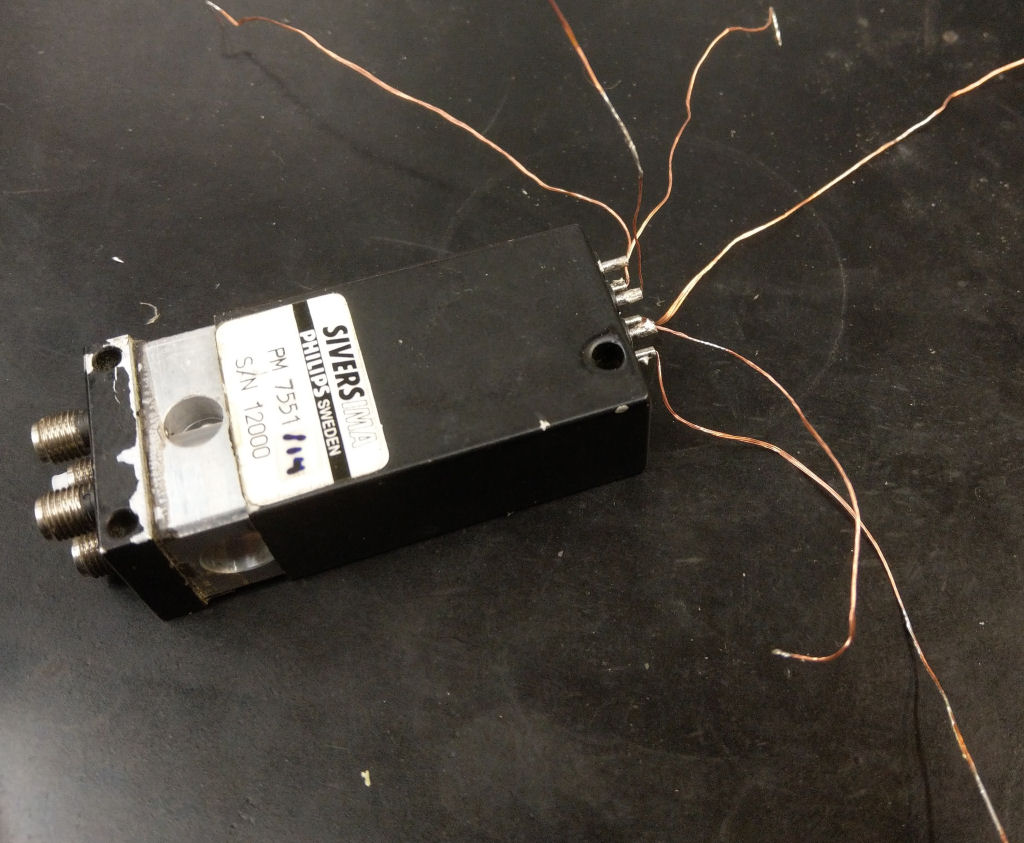
Firstly I had to worry about how the wire connections would be made to the tags at the closed end of the casing, sure enough, teasing the main Relay body out of the case tore the wires off the inside of the stubs and at that stage it felt like 'bye bye Relay'.
IMAG0287e.jpg
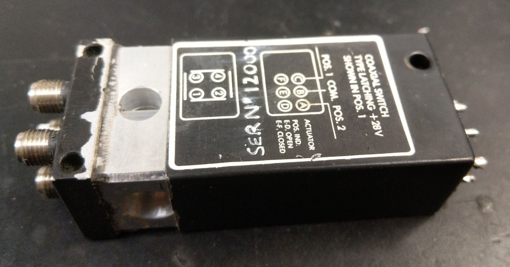
IMAG0287e.jpg (85.68 KiB) Viewed 4095 times

Once open, I was impressed by the quality of the mechanism although confused by the wiring through two multi contact leaf switches.
It was immediately obvious that there was some light rusting of various metal parts, trying to prod the relay drum between states showed that not only was it sticky in operation but also that two plastic pegs operating the leaf switches were stuck too.
IMAG0288e.jpg
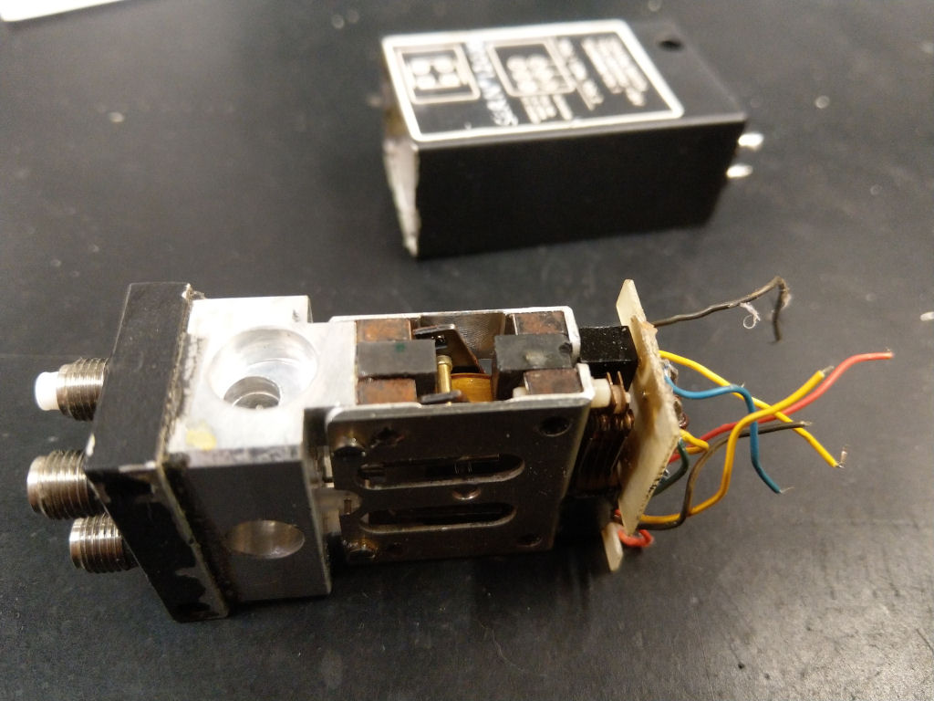
IMAG0288e.jpg (117.75 KiB) Viewed 4095 times

A good clean up of the drum assy and lubricating the pivot points soon freed up the drum, then the operation was being obstructed by the plastic pegs. One cleaned up in situ but I had to remove the leaf switch for the other in order to remove it completely before it would clean up sufficiently.

Then I had to work out which wires went to where so that I could get them back to the correct tags. This took longer than I thought and had to resort to making a circuit diagram.
IMAG0290e.jpg
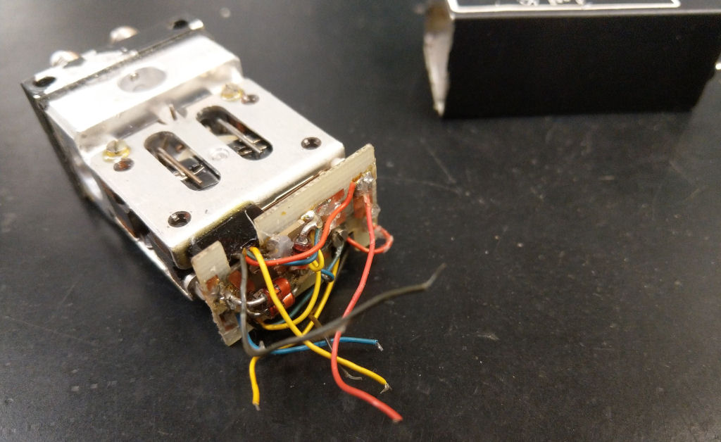
IMAG0290e.jpg (105.68 KiB) Viewed 4095 times

Finally I had to fathom some method of getting the wires back.. It took a while to come up with a plan... I Cleaned out the small tube stubs on the casing by using a resistor wire with the Soldering Iron then finally added a far greater length of bare wire to extend the torn wires enough (and replaced two completely) to be able to feed them into the stubs by hand, it was then just a matter of pulling the wires through slowly as the relay was eased back into the case.
IMAG0292e.jpg
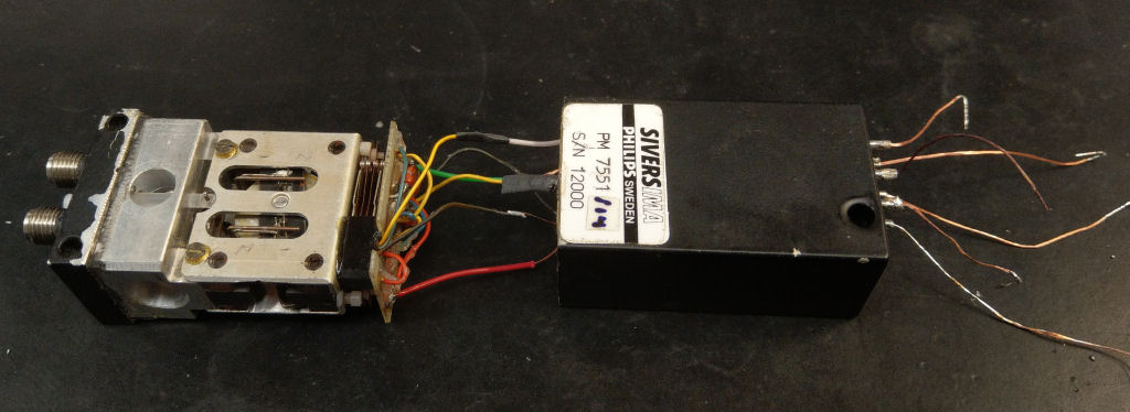
IMAG0292e.jpg (72.47 KiB) Viewed 4095 times
IMAG0293e.jpg
IMAG0293e.jpg (141.61 KiB) Viewed 4095 times

Then a last check the operation before snipping off the excess wires and finally seating the body back in the case. Job done and now ready to use.
:
Dah-di-dah
:
Graham G8VAT

Post Reply

Return to “General ATV Discussion”