
Hi Guys
Not sure if anyone can offer help but here goes.
I am trying to figure out the 3 element phased array that drives the quadloop antenna. Using the loopquad.exe program to design an antenna I am very baffled as to how to construct the 3 element phased array that drives the loop.
the said program gives you the dimensions of the 3 driven loop lengths and it gives the spacings but it fails to mention how to connect the the 300Ohm
phasing line that the elements are soldered to, or what the length and the height of the line.
Also how is this line fed?
I have emailed via the website on several occasions but never got a response, not sure if G3JVL is SK?
Anyway if any of the gurus on here have designed and built a JVL quadloop with the wideband driven array could you be kind to post a bit of a guide for me as to how this feed is built and set up.
I look forward to any help offered.
http://www.g3jvl.com/programPages/loopQuad.php
Cheers Mark
3 element phased driven element on quadloop
Forum rules
This forum is run by the BATC (British Amateur Television Club), it is service made freely available to all interested parties, please do not abuse this privilege.
Thank you
This forum is run by the BATC (British Amateur Television Club), it is service made freely available to all interested parties, please do not abuse this privilege.
Thank you
Re: 3 element phased driven element on quadloop
Mark
My quadloop is fed with 50 ohm line and only one element is fed. The design is in the RSGB Microwave handbook 1st edition and the VHF UHF manual.
The microwave handbook volume 1 contains details of a logperiodic wideband feed - I assume that's what you are looking at. It's on page 4.10. It looks much harder to build than the simple feed. However, its just like any other logperiodic feed. It does not say what the spacing is but assume its a 300 ohm line, shorted at one end with the feed at the other end. I.e. its like a hairpin. One side of each loop is soldered to the bottom of the hairpin and the other to the top.The elements phase alternates so the middle loop is opposite to the front and back.
I would post a picture but its copyright. The book is so out of date its still providing program listings in BBC basic so I wouldn't propose buying it for just that diagram. A poor quality photocopy of the same diagram appears in the RSGB international microwave handbook, 2nd Edition on P58.
Mike
Re: 3 element phased driven element on quadloop
Hi Mike,
yes I have your version of the design its also in the Volume 3 handbook but it is the single element design and has a narrower bandwidth
Anyway i will look for the Log periodic feed you mention it may be in my volume 3 so will search in there.
OH STOP PRESS!
I have just had an email from G3JVL he'll soon be 80 years old which is good news that he is still around.
He informed me that the dimensions from the program provide the distance from the reflector plate to the front of the smallest loop where the feed point is attached.
Here is the picture he sent.

for 13cms quad he said
"The dimensions given for the broadband version will give plate to feed point.
The picture shows the feed connection at the end with the smaller loop.
The connector is attached to a turned item the passes through the boom and forms the coaxial outer.
I used an N type so the Tee shaped piece had a square shape (bottom).
Take a look and see if you can see what I mean?
Mike"
So with this info from Mike and your help aswell Mike I think I should be able to figure it all out.
but I will still search for the Volume one info for the Logperiodic feed just so I can try to understand the mechanics.
so a big thanks to both Mike's

yes I have your version of the design its also in the Volume 3 handbook but it is the single element design and has a narrower bandwidth
Anyway i will look for the Log periodic feed you mention it may be in my volume 3 so will search in there.
OH STOP PRESS!
I have just had an email from G3JVL he'll soon be 80 years old which is good news that he is still around.
He informed me that the dimensions from the program provide the distance from the reflector plate to the front of the smallest loop where the feed point is attached.
Here is the picture he sent.
for 13cms quad he said
"The dimensions given for the broadband version will give plate to feed point.
The picture shows the feed connection at the end with the smaller loop.
The connector is attached to a turned item the passes through the boom and forms the coaxial outer.
I used an N type so the Tee shaped piece had a square shape (bottom).
Take a look and see if you can see what I mean?
Mike"
So with this info from Mike and your help aswell Mike I think I should be able to figure it all out.
but I will still search for the Volume one info for the Logperiodic feed just so I can try to understand the mechanics.
so a big thanks to both Mike's
Re: 3 element phased driven element on quadloop
I have an original G3JVL constructed loop yagi with the 3 element log periodic feed. I will be pleased to take dimensions or post photographs if required.
73 Shaun G8VPG.
73 Shaun G8VPG.
Re: 3 element phased driven element on quadloop
Hi Shaun,
I would be grateful for you to take photos dimensions of the G3JVL Loop antenna.
I am about to build one so would be very useful .
Regards Steve
I would be grateful for you to take photos dimensions of the G3JVL Loop antenna.
I am about to build one so would be very useful .
Regards Steve
Re: 3 element phased driven element on quadloop
Steve,
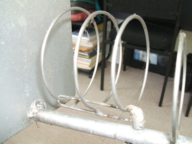
Herewith details of the G3JVL log-periodic quad loop feed. This one was built by G3JVL and works well.
The elements are formed from stainless steel wire 2.4mm diameter and joints brazed.
The front loop is 74mm diameter, middle 78mm and rear 82mm (all outside diameters including thickness of wire).
The front loop is very close to the connector and the spacings between the loops is 24.5mm, net space not including wire thickness.
The trombone is 76mm long, 11mm high including wire thickness.
Spacing rear loop to reflector 42mm.
Spacing front loop to first director 33mm.
Please let me know if you need any further information.
73 Shaun.
Re: 3 element phased driven element on quadloop
That's interesting,
Mine have a securing screw through the boom attached at the rear end of the feeding loop (parallel to the boom).
I assume that must be a low voltage point...
On a side note, If you ever break some of the brazed joints you can successfully repair them with silver solder (55% silver) and a blowtorch
Rob
Re: 3 element phased driven element on quadloop
Thanks all for the input, hopefully this will help others to attempt the JVL quadloop, I wonder if the stainless steel wire is a must, as I was thinking of normal copper wire, would the losses be restrictive or am I better to suck it and see?
Anyway thanks again for the help and pictures.
Cheers Mark
Anyway thanks again for the help and pictures.
Cheers Mark
Re: 3 element phased driven element on quadloop
Copper is a better conductor than steel, so I expect that it would work well.
73 Shaun.
73 Shaun.