Page 1 of 2
Switching stuff from PTT
Posted: Sun Oct 07, 2018 8:45 am
by g0mjw
Making use of the very cheap PCB offers currently available I have made a simple high side switch to connect 12V on grounding, e.g to drive a relay or a small amplifier. Its limited by its lack of heatsinking to a couple of amps. I will put the gerbers in the files area on the Wiki. I built one up with an IRF9540 rather than an IRF9520 as the higher current devices were more available. To switch more power, heatsinking of the device will be required - that's fairly easy to do with the TO220 versions of the devices, keeping the high current paths off the PCB.
Mike
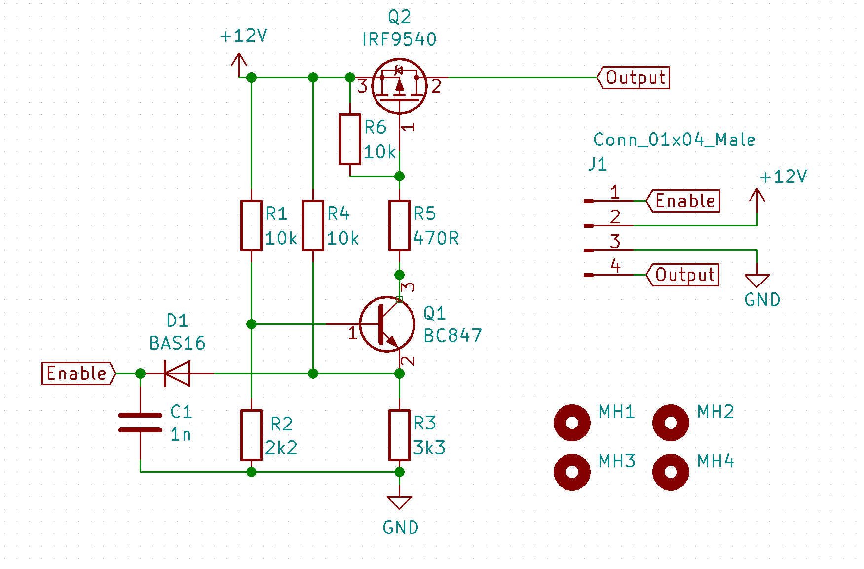
- HSSwitchSchematic.PNG (48.6 KiB) Viewed 7947 times
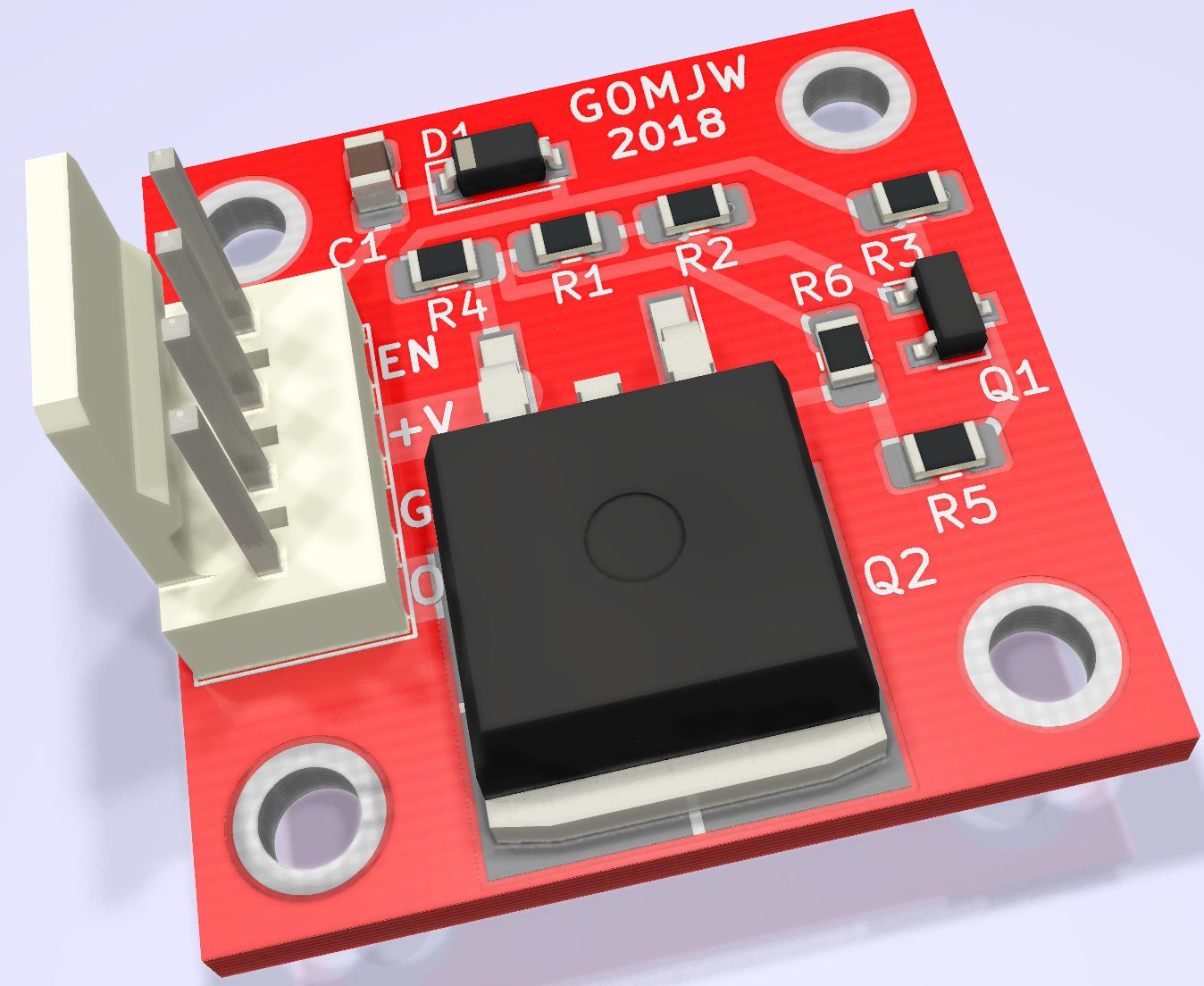
- HSSwitchModel.jpg (143.89 KiB) Viewed 7947 times
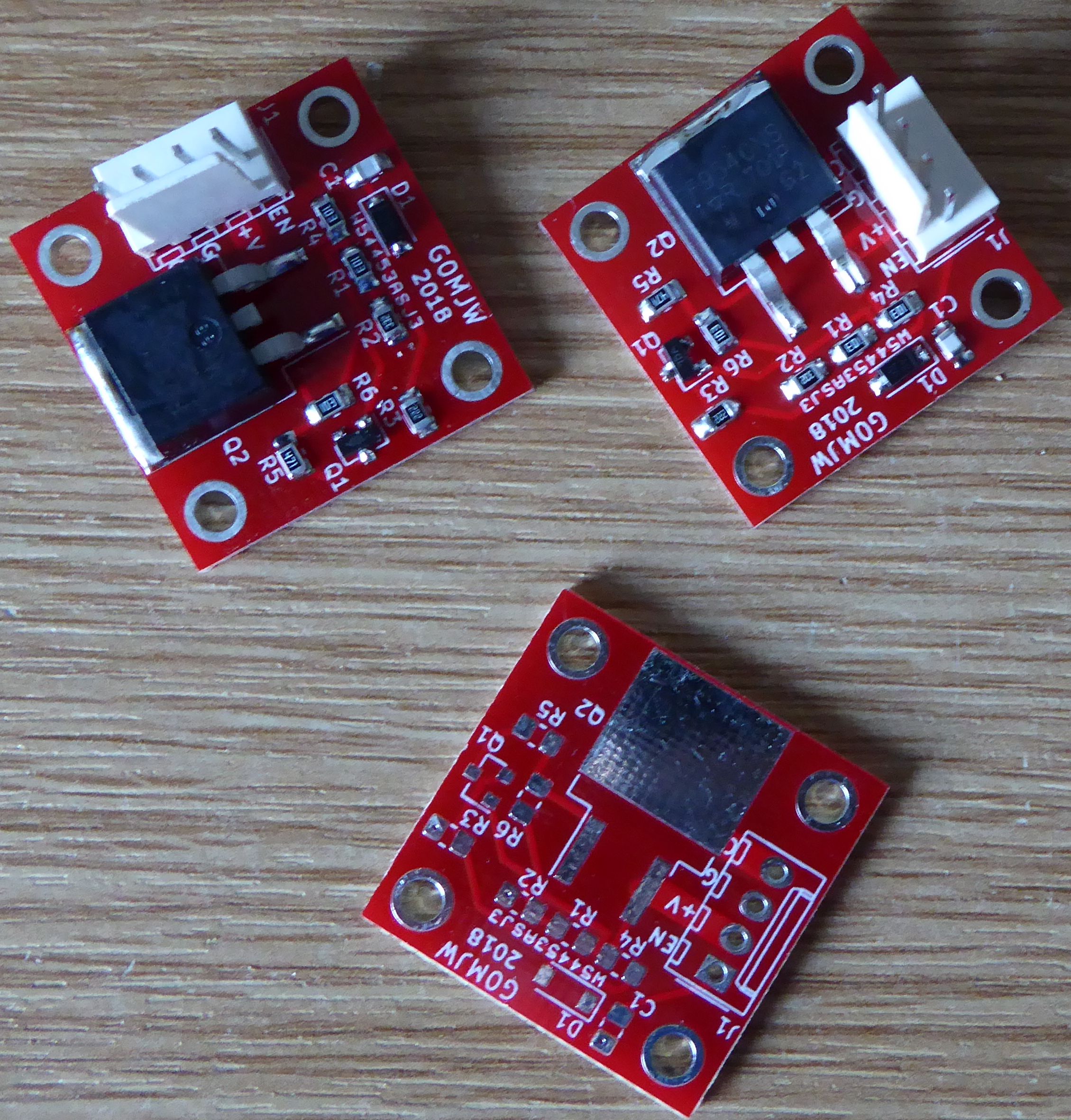
- HSSwitch.jpg (848.87 KiB) Viewed 7947 times
Re: Switching stuff from PTT
Posted: Sun Oct 07, 2018 10:30 am
by gm1mfn
That looks like an interesting biassing arrangement for Q1.
Re: Switching stuff from PTT
Posted: Sun Oct 07, 2018 1:10 pm
by g0mjw
Yes, after building it I agree R2 could be a bit lower, maybe 2k2, or R3 3k3. You don't need to pull it very hard to turn it on so perhaps a bit too sensitive.
Q1 is not really needed for a simple switch, you could just ground the gate of Q2 as long as the higher voltage didn't upset your driving I/O. Grounding the base of Q1 (shorting R2) will turn it back off again. I should add a pad to make that connection easier.
Re: Switching stuff from PTT
Posted: Sun Oct 07, 2018 3:57 pm
by gm1mfn
The values of R2 & R3 suggest that Q1 is actually always turned on slightly, with 3.04V on the base and 2.16V on the emitter from a 12V supply. This means that Q2 is never fully turned off. It would get worse if the 12V supply is actually a car battery on charge at 14.2V.
It might be better to make R2 2k2 & R3 3k3 then the base emitter junction of Q1 would be reverse biassed with nothing connected to the input.
Re: Switching stuff from PTT
Posted: Sun Oct 07, 2018 4:14 pm
by g0mjw
Indeed, I may well have transposed them when drawing it out. Easy fix.I measured it and its not actually on, the gate is at 10.8V with a 12V supply and the threshold is 4V.
(Don't seem to be able to delete old attachments...)
Re: Switching stuff from PTT
Posted: Mon Oct 08, 2018 7:44 am
by gm1mfn
There appeared to be only one attachment to your first post and I have deleted it for you. You'll need to put the correct one back.
73
John
Re: Switching stuff from PTT
Posted: Mon Oct 08, 2018 7:59 am
by g0mjw
I re-uploaded last night but I don't have these attachments any more so please can you put them back?
Re: Switching stuff from PTT
Posted: Mon Oct 08, 2018 8:46 am
by gm1mfn
Humble apologies, I didn't anticipate that and didn't download it before deleting. I think it's probably gone from the server now so can't be restored.
Re: Switching stuff from PTT
Posted: Mon Oct 08, 2018 1:17 pm
by MN-tech
I can't find the schematic you are discussing but I do want to add that there are many ICs made for this purpose. They take a logic level in and switch a higher voltage. Digi-key calls them " PMIC - Power Distribution Switches, Load Drivers".
Here is one high current example. BTS500551TMBAKSA1
https://www.digikey.com/product-detail/ ... ND/2051619
John
Re: Switching stuff from PTT
Posted: Mon Oct 08, 2018 3:45 pm
by g0mjw
gm1mfn wrote: ↑Mon Oct 08, 2018 8:46 am
Humble apologies, I didn't anticipate that and didn't download it before deleting. I think it's probably gone from the server now so can't be restored.
Strange. I found them on FB uploaded again and the old ones re-appeared!