Page 3 of 4
Re: RT5047 U3 and U4
Posted: Sat Mar 27, 2021 1:34 pm
by g0mjw
Sensible substitutions are fine, as long as they fit the PCB. I am sure it doesn't need a 2.5A inductor, that's overkill but I went for what had been used successfully before. For the chip it is best to solder the pins first and then the do bottom tab through the hole. Note you don't really need the protection diode on the back as it's being run from the 12V supply.
Mike
Re: RT5047 U3 and U4
Posted: Sun Mar 28, 2021 10:29 am
by G0LJF
Hi Mike
I agree - the PCB is not going to magically change to suit.
Well I am the Guinea Pig here - I have ordered all these Farnell parts and then I am going to build it. My BATC shop PCBs/NIMs should be in the post now.
One last question, the Hammond box has some guide rails for PCBs to simply slide in. I have this.
Does the PCB fit into these, or do you use spacers and screws as I suspect from the photographs and PCB? I don't yet have a board here to examine.
And presumably these should be short to avoid the NIMs fouling the top of this box.
73, Mike
Re: RT5047 U3 and U4
Posted: Sun Mar 28, 2021 12:57 pm
by g0mjw
The PCB slides in. The TO220 devices need to bolt to the side for cooling. It will be easier to drill the holes for this if you adjust their height so that the holes fit into the groove of the box rather than on a ridge. Don't drill the holes until you can test assemble it with your rear panel. The PCB should be flush to the rear panel but it's hard to measure that before you cut the panel holes. It's slightly beyond the main box chassis because of the plastic surround.
I would build and test it all first before thinking about putting it in the box and in particular do those mounting TO220 holes holes last. Before you fit the fan, use the PCB to mark out its position on the base of the box which will help locate the holes for air ingress. Drill some large holes e.g. 6mm in the back panel between the NIMs for air exit. The NIMs get hot and need a light airflow.
Mike
Re: RT5047 U3 and U4
Posted: Sun Mar 28, 2021 1:23 pm
by G0LJF
Thanks Mike,
All good advice. I did see you mention the NIM heat removal problem on the last BATC net - your array of cooling air holes was very impressive.
I usually scribe a circle (and then others within) as this is easy to divide into six holes. Triangles are a new idea.
If I had the PCB in front of me it would be easy.
I thank you for the tip about mounting the regulators - I would have missed that one if I were too hasty.
73, Mike
Re: RT5047 U3 and U4
Posted: Fri Apr 02, 2021 7:50 pm
by G4KLB
Here's one I prepared earlier. (has the R4.R5 pull ups fitted as needed for the production main boards)
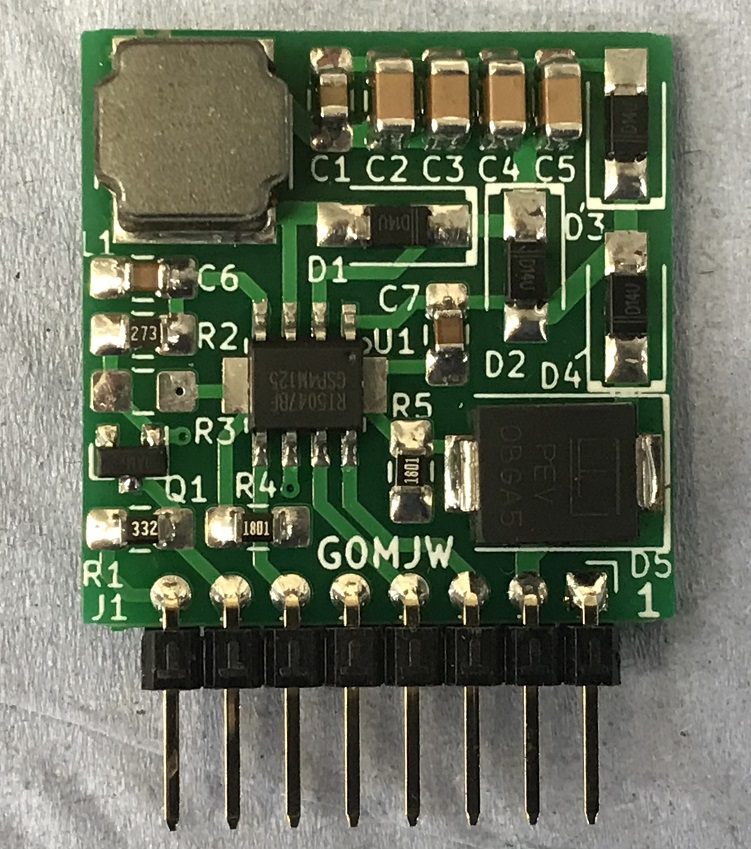
- RT5047-.jpg (259.53 KiB) Viewed 6795 times
Re: RT5047 U3 and U4
Posted: Fri Apr 02, 2021 8:20 pm
by g0mjw
Colin - can you add that to the Wiki?
Mike
Re: RT5047 U3 and U4
Posted: Sun Apr 04, 2021 4:40 pm
by G0LJF
Hi Mike,
I can confirm that those Farnell parts I selected all work fine.
I just tested it with a 30R resistor and it was able to supply 13V fine, and the 18V caused the short circuit overload LED to flash, as was expected.
So that's 433 mA on 13 V OK, and 600 mA on 18 V, overload condition.
I used a 68 R to check the 18 V and that was delivering 264 mA and working fine. The RT chip was not getting warm.
One thing, I could not get the 10 uH SMD inductor (on back order) so I used this leaded part from CPC PW00009.
Fit it horizontally on the board as it sticks out of the back of the main WH PCB - and there is currently nothing there to foul if you use the selected case.
Lastly, if you only have only one RT board, fit this in the U4 slot and not U3 as I did. Otherwise it cannot be controlled from Quick Tune.
I think this is important to note.
I am going to fit the second RT board when I receive it from BATC shop.
And finally, I soldered the lot in one operation (well 30 seconds) using 'proper' Lead alloy solder paste (CPC SD02698) and my hot air gun. I used a domestic electric cooker hot plate pre heated to 150 C for ten minutes, to stabilise, to pre-heat the assembled PCB first. The components on the reverse side I soldered by hand.
Update: My second RT board is now completed, installed, and tested. Solder paste makes it easy, maybe a bit off square but works FB.
73, Mike
Re: RT5047 U3 and U4
Posted: Wed Aug 02, 2023 6:23 pm
by DL5BCA
Hello,
I got a used Winterhill today. It starts and I was able to update.
But now I also need 18 volts on the LNB and there is no LNB supply PCB for BATC Advanced receiver installed.
I still have a stepup converter.
Can I also connect this to the corresponding input (NIM TOP A - middle PIN)?
Or is the LNB supply PCB for BATC Advanced receiver still being queried somehow?
73 Thomas DL5BCA
Re: RT5047 U3 and U4
Posted: Wed Aug 02, 2023 8:03 pm
by G4EWJ
Connect 18v to the middle pin of the three pins in row "NIM A TOP" and column "SELECT SUPPLY ([X/Y] OR 12V)". Remove any jumpers.
There will not be any short circuit protection, so remove power from WH and the step-up converter when connecting the LNB cables to the NIMs.
Brian
Re: RT5047 U3 and U4
Posted: Thu Aug 03, 2023 6:12 am
by DL5BCA
Hallo Brian,
thanks for the hint.
I will install a 500mA PTC fuse. At least that gives me a little security.
73 Thomas