Hi all,
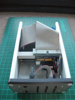
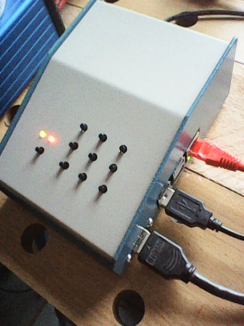
To give you an idea of my case, here it is.... Farnell order code 1456CE2WHBU. 51 mm X 102 mm X 140 mm. 2mm thick Aluminium - so I hope you enjoy filing as much as I try to avoid it.
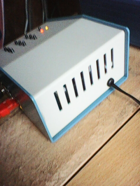
Its all a bit tight so just be careful, if you duplicate my idea. Take your time. Some small room for expansion, and any 3.5 mm audio jack would also need an extension from the Pi.
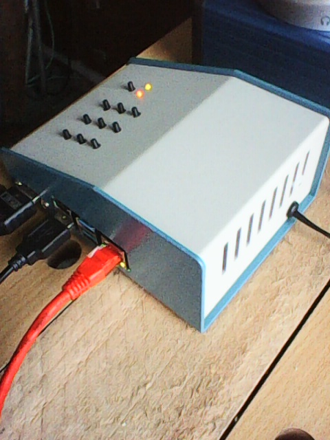
I used a micro HDMI to HDMI cable and I hot melt glued the switch panel in place, and the IR receiver module. I did not want to see screws on the front.
The PSU is external, and a RPi 3 type (2.5 A).
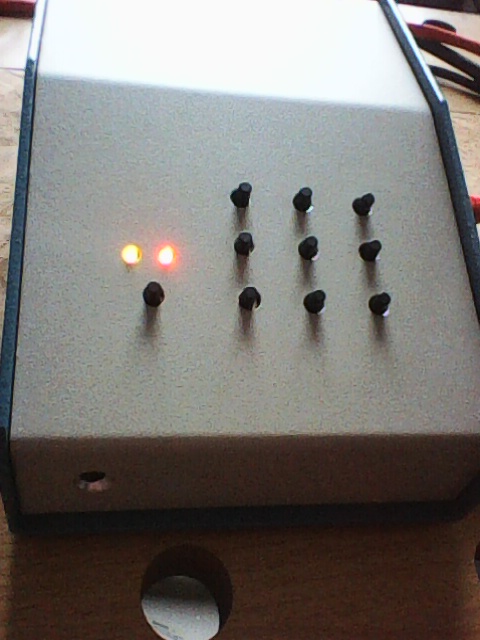
Drilling the switch hole matrix was not easy and I have made a few errors, so take care.
The Pi is mounted on three metal stand-offs as the lower case half has ventilation slots in the way of number four.
I would also strongly recommend using a metal case, as the RPi 4 generates QRM on 70 MHz. Not seen much on 50 MHz. And therefore, keep your Knucker Rx and MT Rx well away, in their own metal cases if you use these lower VHF bands. And remove the Ethernet cable when not in use and ferrite the PSU lead.
- Photo0063.jpg (103 KiB) Viewed 2607 times
- Photo0062.jpg (90.28 KiB) Viewed 2607 times
- Photo0061.jpg (86.42 KiB) Viewed 2607 times
- Photo0060.jpg (101.87 KiB) Viewed 2607 times
73, Mike