Page 1 of 21
Langstone Discussion Forum
Posted: Sat Apr 11, 2020 1:54 pm
by G8GKQ
I have established this new Forum for discussion about the Langstone narrowband microwave transceiver, which is based on a Raspberry Pi 4 with a 7 inch touchscreen and an Analog Devices Pluto SDR.
It is currently in the development stages and is described on the UK Microwave Group Wiki here:
https://wiki.microwavers.org.uk/Langstone_Project. The code can be found on GitHub here:
https://github.com/g4eml/Langstone.
The Langstone was initialy intended as a technology demonstrator for the "Hayling" project
https://wiki.microwavers.org.uk/Hayling_project but is now being built by at least 6 BATC members and seems to have much of the functionality originally planned for the Hayling. A frequency waterfall display capability is under development.
Please note that the system needs to be built with the exact hardware specified on the Wiki (if you want it to work first time) as it is in an early stage of development. A typical hardware implementation is shown below.
This project may well converge with the "Portsdown on Raspberry Pi 4", but Portsdown needs a major rewrite to work on this version of Raspberry Pi, so it won't happen soon.
Dave, G8GKQ
Re: Langstone Discussion Forum
Posted: Sat Apr 11, 2020 2:09 pm
by G7JTT
Waiting for the LimeSDR support

looks to be a great companion to the Portsdown

All the best and stay safe John
Re: Langstone Discussion Forum
Posted: Sat Apr 11, 2020 2:55 pm
by G4KLB
Off to a good start

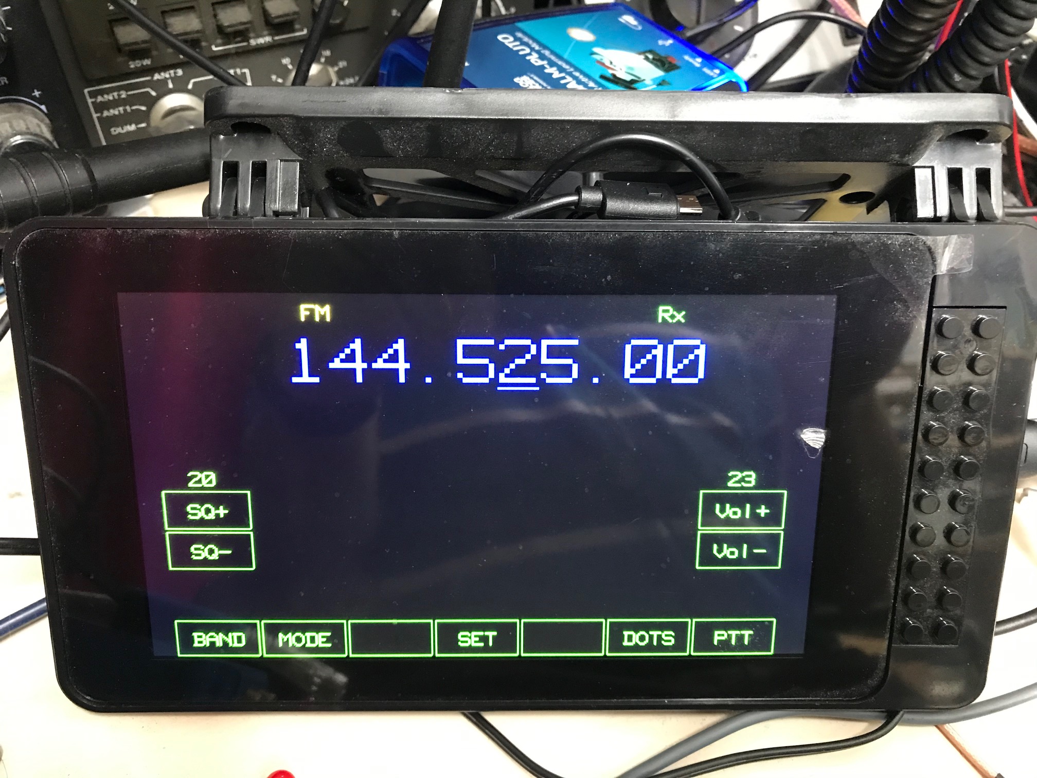
- IMG_1446.jpg (668.41 KiB) Viewed 493114 times
Re: Langstone Discussion Forum
Posted: Sat Apr 11, 2020 8:52 pm
by g4eml
As Suggested by Dave I have modified the GPIO pin assignments to be more compatible with the existing Porstdown use and updated the github source.
GPIO Pin usage is now...
Pin 11 PTT input. Needs to be pulled up to 3V3 with a 4K7 resistor. PTT switch connects between this pin and ground.
Pin 12 KEY input. Needs to be pulled up to 3V3 with a 4K7 resistor. Key connects between this pin and ground.
Pin 40 PTT Output. Goes high when the Langstone is transmitting. Can be used to key external amplifiers and antenna changeover.
Pin 28 Band bit 0. (Portsdown Band D0)
Pin 35 Band Bit 1. (Portsdown Band D1)
Pin 7 Band Bit 2. (Portsdown Transverter Select)
Pin 22 Band Bit 4.
The 4 Band bits can be programmed for each band from the Setup menu. They can be used to select external Transverters or amplifiers.
Note:- The band bits and the PTT Output go to 3.3V when active. It will be necessary to externally buffer these pins to avoid damage to the raspberry pi.
Colin G4EML
Re: Langstone Discussion Forum
Posted: Sun Apr 12, 2020 1:31 am
by G4KLB
Thanks Colin,
I have done that update.
10 minuets after I attacked my Smarti pi case with a dremel to accommodate a RPi4 the Smarti pi Touch 2 turned up

for this development case I had to switch the screen orientation with sudo nano /boot/config.txt and rem out lcd_rotate=2.
Don't know if that's the correct way to do it but it works.
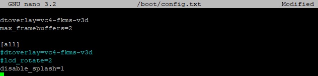
- pi4.jpg (15.9 KiB) Viewed 493040 times
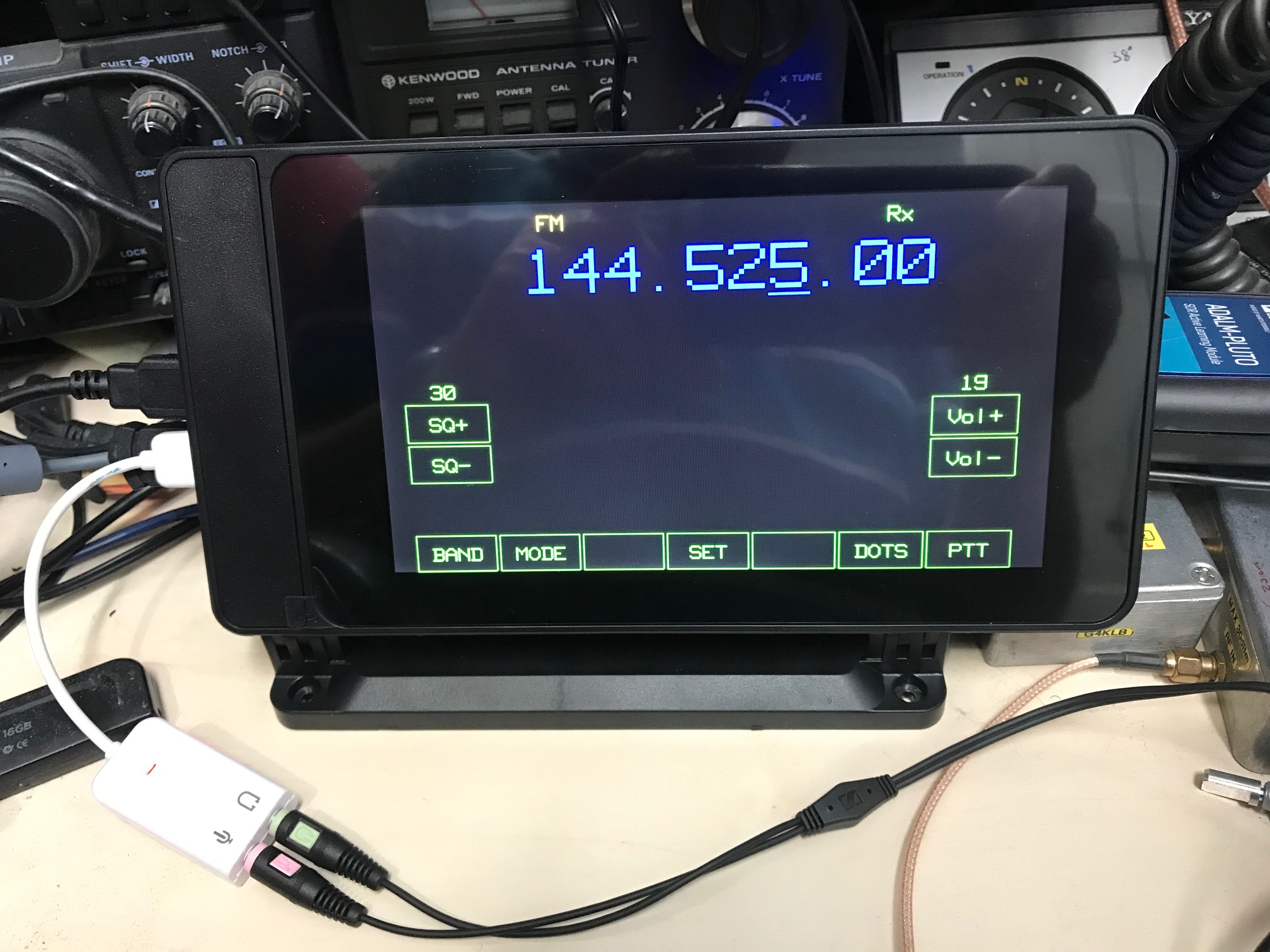
- IMG_1447.jpg (643.53 KiB) Viewed 493040 times
Re: Langstone Discussion Forum
Posted: Sun Apr 12, 2020 9:43 am
by g4eml
Yes,
Commenting out lcd_rotate=2 is the correct way to do it.
I added that to the build script because my original case mounted the LCD upside down.
I will probably leave it there as it’s easier to comment it out than to have to remember the syntax and enter it.
Colin.
Re: Langstone Discussion Forum
Posted: Sun Apr 12, 2020 9:50 am
by g0mjw
I wondered about that - my first case was the same but it's not in that at the moment. I suppose we might consider what way round we want it. Landscape or portrait as we have the opportunity. I think I prefer landscape.
Are we at the stage where we know all the front panel controls? I ask as it's maybe time to think about an enclosure.
Mike
Re: Langstone Discussion Forum
Posted: Sun Apr 12, 2020 11:04 am
by g4eml
The number of controls and connectors is probably a personal decision.
I would think a minimum list would be:-
On the front panel:-
Rotary encoder for tuning, connected to mouse board scroll wheel.
Three push buttons connected to the mouse board.
(Left and right are used for tuning steps, center will be used to select volume or tuning.)
Microphone socket.
Earphone socket.
Key socket.
Power switch. (This may eventually be used to request an ordered shutdown of the Pi.)
Possibly an analog volume control if you prefer this to using the tuning knob.
On the Rear Panel:-
D.C. input socket
Tx socket
Rx socket
Multi-way socket for control of external devices. (Din or D type?)
On any panel:-
Speaker grill.
I am sure others will contribute to this list with optional extras.
Colin G4EML
Re: Langstone Discussion Forum
Posted: Sun Apr 12, 2020 11:46 am
by G8GKQ
Hi Mike
In addition to Colin's list, I have added a multipin mic socket, so that I can use normal fist mics (with PTT switch) and also a manual PTT toggle switch. On the back (well actually the side) I have added an RJ45 socket and will add a USB socket in due course to plug in the MiniTiouner (don't get too excited yet!).
Dave
Re: Langstone Discussion Forum
Posted: Sun Apr 12, 2020 11:54 am
by g0mjw
Good ideas. Any PCBs need making?
 looks to be a great companion to the Portsdown