Page 1 of 2
Developing the G8ADE sequencer [CQ-TV 125] for Portsdown
Posted: Wed Nov 01, 2017 9:10 pm
by M0YDH
Hello Dave and co
I'm under way with my development circuit featuring G8GKQ's transistor changeover switch from the Beginner Question - Complete System thread and Ian Waters' sequencer from the Wiki. See picture. The jumper is in and the test slide switch takes the place of Portsdown Band selection PTT.
I've learnt that turning it on means pulling the J2E terminals to ground and that both 1K resistors in the sequencer are important to making the switch work. So on second attempt, after consulting the analogue electronics engineer at the other end of the office, I've wired it correctly.

Snag pins 3 and 10 remain fast a 0V so no relay action. 12.2VDC supply
I measured IC pin 2 changes from 1.02 to 6.62 V while pin 9 goes 5.8 to 2.02 and vice versa. Pin 1 changes 0.5 - 3.3 V and pin 8 changes 1.02 - 2.9V therefore the RC part is working.
I guess the transistor bias is not sufficient to reach the high threshold voltage of the AND gate? Any ideas? What voltage values did you consider in your design Dave? In case I've a hidden fault in my work. It's partially working which is a crumb of comfort.
There are two unused gates on that device and I would like a 3 band Portsdown with sequencing .....
73
David M0YDH
Re: Developing the G8ADE sequencer [CQ-TV 125] for Portsdown
Posted: Wed Nov 01, 2017 11:43 pm
by G8GKQ
Hi David
I was aiming that the voltage swing should be from 0 to about 10.5v. Calculation for the high voltage is (12-Vce sat)*1000/(1000+100). Vce sat should be about 0.4V.
With the switch input grounded, please check the voltages on the base, emitter and collector of the first transistor. Base should be about 11.3v , emitter 12v and collector 11.6v.
Dave
Re: Developing the G8ADE sequencer [CQ-TV 125] for Portsdown
Posted: Thu Nov 02, 2017 7:33 pm
by M0YDH
Hi Dave
BC214
12.2v collector
11.51v base
7.28 emitter
On my breadboard I've redone the circuit with 2N3906 transistors and added the 1K resistors off the sequencer from the 100R resistor to connect to ground. Voltages at tx 100R are 11.03 / 1.03V and at rx 100r are 0.0004 / 11.1 V. That would work permanently if I moved those 1K resistors to the respective transistor circuit?
Cheers
David
Re: Developing the G8ADE sequencer [CQ-TV 125] for Portsdown
Posted: Thu Nov 02, 2017 7:46 pm
by G8GKQ
Hi David
I think that you had wired the BC214s incorrectly, as the emitter should be at 12V, the base 11.3V and the collector 11.6V.
The indications with the 2N3906s are correct, so you should connect those up and it should work.
Good luck
Dave
Re: Developing the G8ADE sequencer [CQ-TV 125] for Portsdown
Posted: Fri Nov 03, 2017 9:05 pm
by M0YDH
Thanks Dave for the observations.
Andy Britton my colleague at work had sketched in the 1K pull up resistors mentioned above and today I noticed there were diodes after these.
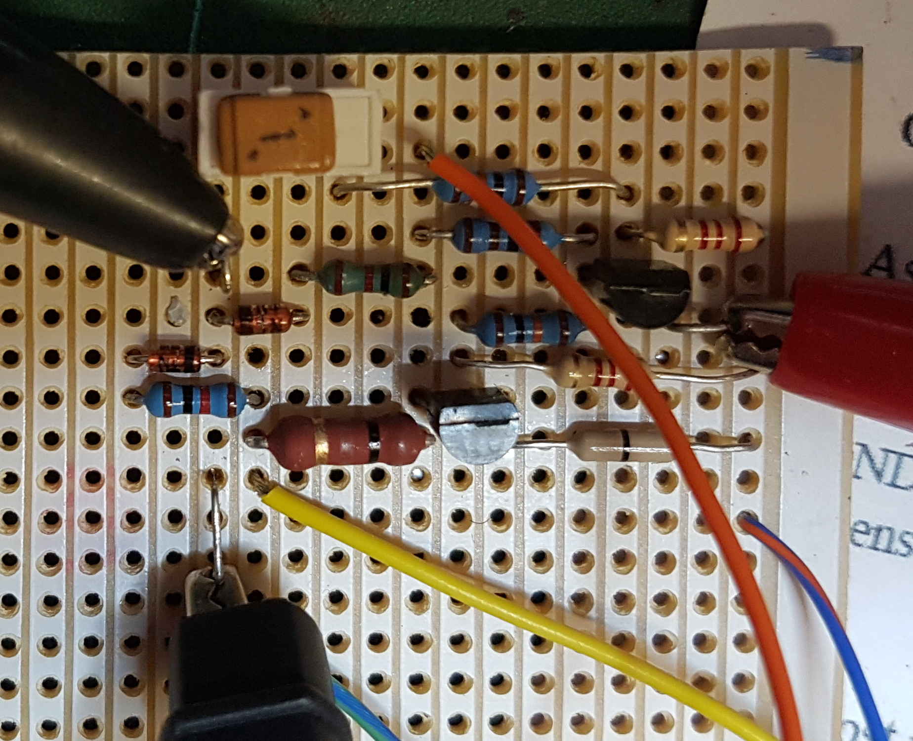
- 20171103_sequencer changeover switch.jpg (213.61 KiB) Viewed 5729 times
This works very well

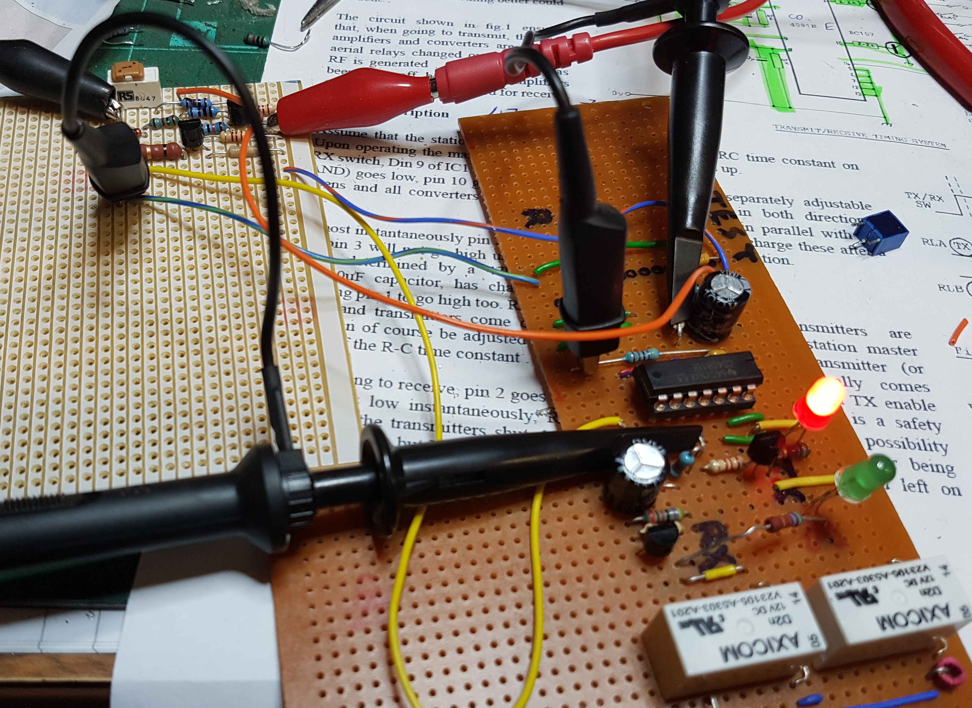
- 20171103_Sequencer test circuit.jpg (558.86 KiB) Viewed 5729 times
Although the LEDs stay on together for 4 seconds the scope trace comparing pins 3 and 10 of the IC looks like this:-
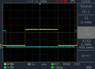
- DS0002.jpg (28.17 KiB) Viewed 5729 times
Both off / changeover time is c. 2.3 seconds at present. I think I'll change the 47K resistor for RC timing to a trim pot.
I'll re-measure at the relays when I've mounted them in a better place.
To-do next is make a fair version on one board or two stacked QRP-Labs style. I wonder if I can use the other 2 gates for other pre-amp power and relay signals running on the same switch interval? Then work out what to do to make a Portsdown 3 band system.
I think I'll make my 70cm DK7ZB beam tomorrow while it's raining. B&Q materials plus John GM8OTI's SOTA friendly construction techniques.
73
David M0YDH
Re: Developing the G8ADE sequencer [CQ-TV 125] for Portsdown
Posted: Mon Nov 13, 2017 5:27 pm
by M0YDH
Updated schematic of this switch is shown below.
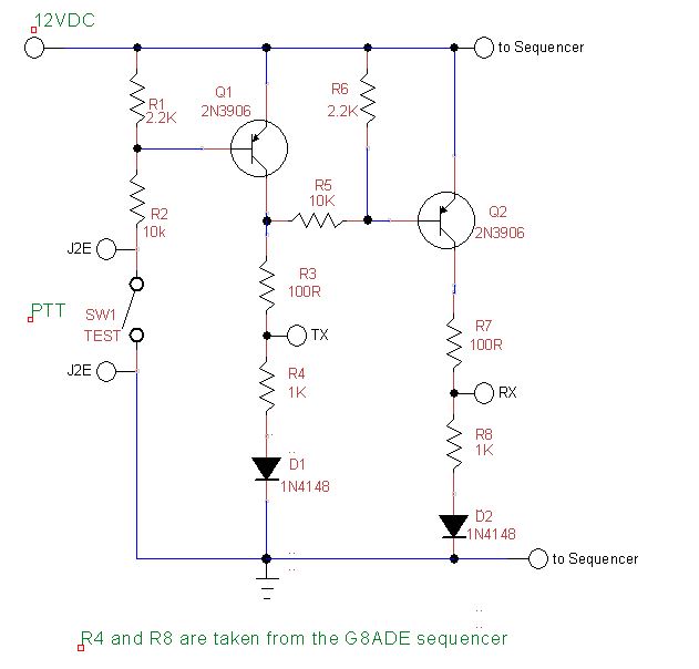
- PTT Changeover Switch schematic.JPG (43.08 KiB) Viewed 5622 times
It was drawn in TinyCAD.
73
David M0YDH
Re: Developing the G8ADE sequencer [CQ-TV 125] for Portsdown
Posted: Sat Dec 02, 2017 11:18 pm
by M0YDH
I'm still blundering away at this circuit. Lots of redo and restarts. I should finush it before this Christmas .
Would the team be considering introducing sequencing in the Portsdown software? I imagine just as I finish my sequencer dear Dave G8GKQ will announce a software update to make it obsolete !
All the best
David M0YDH
Re: Developing the G8ADE sequencer [CQ-TV 125] for Portsdown
Posted: Mon Jan 01, 2018 1:02 pm
by M0YDH
Happy New Year
I made a little film of the basic circuit from CQTV125 in operation with a toggle switch :-
https://youtu.be/u4AeW-bPYxo
Crisp changeover happens at twice the time constant of c. 1.03s each. This is my Mark 5 attempt! I wish I had built the basic circuit first as Mr Waters' design is fine.
Ron M0RNW and I are working on club nights through getting the transistor switch front end to actually change the circuit. It go nicely from high to low volts and back, drives capacitor charging to the half voltage value and doesn't always cause a change of relay state. If I dab +12V onto the end of the connection wire from the switch circuit over goes the relay. It's perplexing.
73
David M0YDH
Re: Developing the G8ADE sequencer [CQ-TV 125] for Portsdown
Posted: Sat Jan 06, 2018 1:32 pm
by M0YDH
Hello all
Happy New Year.
I've made a second video on the relay sequencer
https://www.youtube.com/watch?v=pUudd2GR63w .
The good news is that it's working well (as far as I can tell) but I've abandoned using Dave G8GKQ's transistor switch idea. No matter what arrangement of pull down resistors that I used, I couldn't get a reliable change in output state from the AND gate with the switch. The inputs achieved the same condition of say 11.4V on one imput and half that on the other after capacitor charging as per the original design but no change of gate state. I looked at a circuit on AD5X's website for a seperate antenna Tx/Rx switch and had a play with that on my breadboard. Grounding the emitter of a 2N2222 NPN transistor changes the SPDT relay, turns off Rx relays and starts the Tx Relay. Then Vice-Versa with 2*RC constant as the delay.
I have to move on to the Rx Pre-amp kit from Mini-kits and completing the 70cm Tx amp or I'll never finish a one band system!
73
David M0YDH
Re: Developing the G8ADE sequencer [CQ-TV 125] for Portsdown
Posted: Mon Jan 08, 2018 11:42 am
by M5TXJ
I've built a simple sequencer based on an LM324 quad op amp built into a box with 4 relays, 2 DIL and 2 coax. The idea is the aerial connects to this box and there are connectors for the Minitiouner and the tx amplifier. To use different bands the relevant amplifier output is connected to the sequencer, that's the only change other than connecting the appropriate aerial. On Portsdown going to tx, the sequencer turns off preamp power to the bias tee, grounds the output to the Minitiouner to prevent from leakage in the aerial changeover relay, changes the aerial relay and finally keys the transmit amplifier. I'll post some pictures once it's all boxed up if anyone wishes.
73 Dave