Beginner question - complete system

Discussion about this major DATV Project. See https://wiki.batc.org.uk/The_Portsdown_Transmitter
M0DHP
Posts: 92
Joined: Sun Sep 24, 2017 3:25 pm

Beginner question - complete system

Post by M0DHP » Mon Oct 02, 2017 10:13 am

Hello, just started work on a Minitiouner with a Portsdown next on my shopping list. I plan to operate /P (given limitations of home QTH) so am trying to understand all the boxes and bits I will need to take on the road.

Reading the wiki pages on filters and amplifiers, I think a complete single-band configuration might look something like this (taking 23cm as an example). Have I missed any major blocks, or got things in the wrong place? The diagram does not show power supplies yet and assumes just using the RPi camera.

Many thanks and 73

Ray M0DHP
system 01.png
system 01.png (24.36 KiB) Viewed 5953 times

g0mjw
Posts: 2346
Joined: Sat Sep 20, 2014 9:15 am

Re: Beginner question - complete system

Post by g0mjw » Mon Oct 02, 2017 3:50 pm

Looks right. The bandpass filter could be a problem. Most of these are post types that may have resonances at harmonics. They won't have so much effectiveness at removing the harmonics of the PA. Therefore you may need a low pass filter on the PA output.

Depending on the PA, you may not need a driver amplifier. If it is an RA module for example. Don't expect more than about 25% of the maximum power output, quite possibly less, with acceptable spreading.

Be careful your relay has sufficient isolation to not destroy your pre-amp.

Mike

M0DHP
Posts: 92
Joined: Sun Sep 24, 2017 3:25 pm

Re: Beginner question - complete system

Post by M0DHP » Mon Oct 02, 2017 4:26 pm

Thanks for all the info, Mike.
Therefore you may need a low pass filter on the PA output.
Do you mean I should add a second LP filter on the PA output or move the one from the driver input?

G8GKQ
Site Admin
Posts: 2810
Joined: Sun Mar 22, 2009 1:21 pm

Re: Beginner question - complete system

Post by G8GKQ » Mon Oct 02, 2017 7:47 pm

Hi Ray

You only need a low pass filter on the PA output. No point in having one before that, as the driver/PA will regenerate the 3rd harmonic.

Well done

Dave, G8GKQ

M0DHP
Posts: 92
Joined: Sun Sep 24, 2017 3:25 pm

Re: Beginner question - complete system

Post by M0DHP » Mon Oct 02, 2017 8:39 pm

Thanks, Dave.

Updated diagram.
system 03.png
system 03.png (32.03 KiB) Viewed 5897 times

M0YDH
Posts: 264
Joined: Sat Dec 31, 2016 5:59 pm

Re: Beginner question - complete system

Post by M0YDH » Tue Oct 17, 2017 10:21 pm

hello Dave
I'm struggling to understand how to integrate the PTT and band switching output with a sequencer as seen at https://wiki.batc.tv/PTT_and_band_switching. I have all this to do as the output from the board goes to a sub-D connector.
In the large die cast box that I bought today at Maplins for the Mini-kits amp and LPF there's space I think for some sort of circuits to do these jobs and RCA connectors to the next band items.

regards

David M0YDH

G8GKQ
Site Admin
Posts: 2810
Joined: Sun Mar 22, 2009 1:21 pm

Re: Beginner question - complete system

Post by G8GKQ » Tue Oct 17, 2017 10:51 pm

David

How many bands are you going to transmit on? If it's just one, I'll try to draw you an interconnection circuit.

Dave

M0YDH
Posts: 264
Joined: Sat Dec 31, 2016 5:59 pm

Re: Beginner question - complete system

Post by M0YDH » Wed Oct 18, 2017 6:24 pm

Thanks Dave. I'm building the 70cm set first. I'd like a 23cm set up and, if the NoV is renewed by OFCOM, 2m. So single band to start and 3 bands eventually. :)

g8gtz
Posts: 1736
Joined: Wed Apr 07, 2010 6:26 pm

Re: Beginner question - complete system

Post by g8gtz » Thu Oct 19, 2017 5:49 pm

http://rsgb.org/main/blog/news/rsgb-not ... v-renewal/

Looks like we are good for another year.

73 Noel

G8GKQ
Site Admin
Posts: 2810
Joined: Sun Mar 22, 2009 1:21 pm

Re: Beginner question - complete system

Post by G8GKQ » Sun Oct 22, 2017 9:34 pm

David

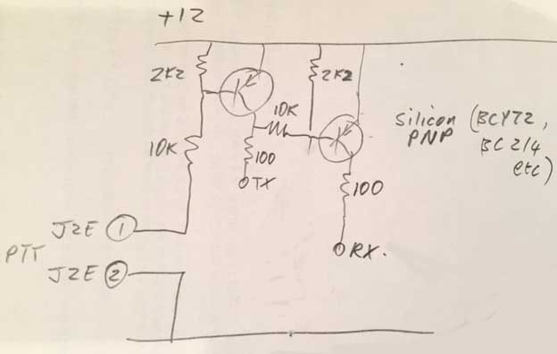
Sorry for the delay. Here's an idea for a circuit to go between the PTT and Band Switch board and G3KKD's timing circuit in CQ-TV 125.

The PTT input from J2E is normally open circuit, so the first transistor is off. The TX output is connected to the TX switch terminal on G3KKD's circuit, which pulls it low. This turns the second transistor on, pulling the receive terminal high. Vice-versa for transmit. The 100 ohm resistors are to limit the current surge on switching that would be caused by the 0.1uf capacitors.

This is for single-band use. For simple multi-band, you could put the band switch outputs from the Portsdown in series with the relay outputs from G3KKD's circuit. The only disadvantage would be that all receive preamps would be turned off during transmit on any band.

Please check the circuit's operation carefully before using it in anger. This is a first draft to give you a starting point - it should work, but no guarantees!

Dave, G8GKQ
Attachments
Switching.JPG
Switching.JPG (40.28 KiB) Viewed 5595 times

Post Reply

Return to “The Portsdown Digital ATV System”