The filter requirements are very basic. You should be able to make them from your junk box. Here are 2 that I have just constructed:
- Filters.jpg (165.56 KiB) Viewed 6568 times
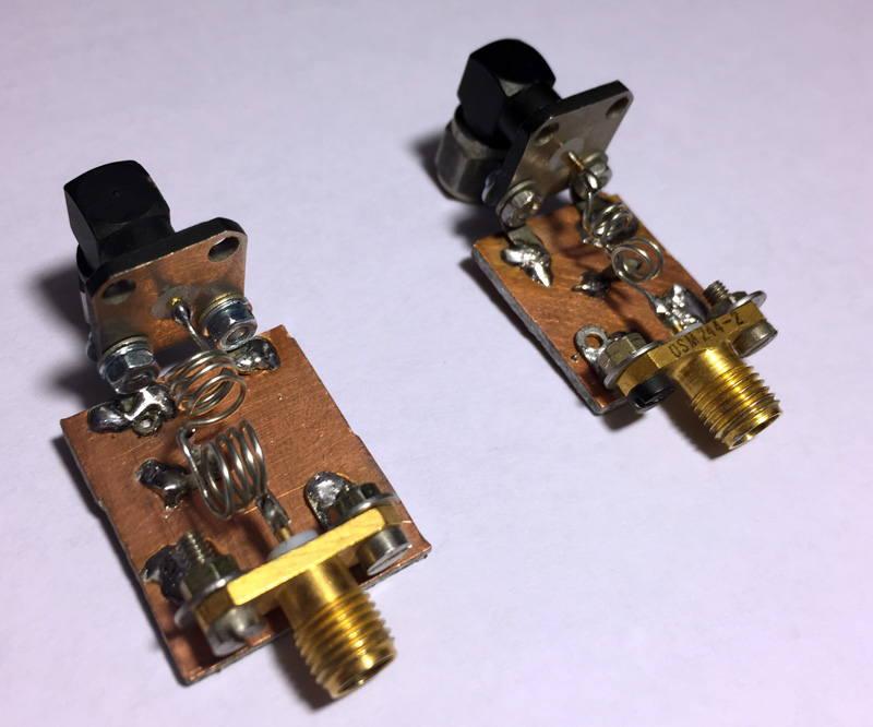
The left hand filter is for 146 MHz. It is series L, shunt C, series L in a T configuration. The inductors are each 4 turns of 24 swg tinned copper wire wound on a 4.5mm drill. The capacitor is 27 pf ceramic. The filter has 1.5 dB insertion loss at 146 MHz and >25 dB loss at 440 MHz. My ADF4351 gives -0.5 dBm when set to output level 3 at 146 MHz, so the input level to the modulator is -2 dBm, which is the recommended level.
The right hand filter is for 437 MHz. Same configuration, the inductors are 2 turns of 24 swg wound on a 3mm drill, and the capacitor is a 4.7 pf ceramic. The insertion loss at 437 MHz was 2 dB and the attenuation at 1300 MHz over 17 dB. The resulting input level to the modulator was about -2.5 dBm. Note that the inductors are at right angles to reduce cross-coupling.
Both filters raised the output MER to 26 dB (measured in MiniTioune 5a). I used a right angled SMA chassis socket on one end of each, so that I could connect them directly to the modulator without another cable. No filter is required for 1255 MHz.
The software-switched filter board has been designed and we are just waiting for the Chinese to finish celebrating New Year before getting the prototypes made. In the interim, these manually installed filters will do the job.
Dave, G8GKQ
